Electromagnetic flowmeter

An electromagnetic flowmeter and excitation current technology, which is applied in the application of electromagnetic flowmeters to detect fluid flow, volume/mass flow generated by electromagnetic effects, etc. Improve dynamic response performance and output stable effect

Active Publication Date: 2012-09-05
SHANGHAI WELLTECH AUTOMATION CO LTD +1
View PDF7 Cites 16 Cited by
  • Summary
  • Abstract
  • Description
  • Claims
  • Application Information

AI Technical Summary

Problems solved by technology

[0005] The purpose of the present invention is to provide an electromagnetic flowmeter that can generate an excitation current with an excitation frequency divided by a non-even multiple of the power frequency to solve the problem in the prior art that the excitation frequency of the excitation current is limited to an even multiple of the power frequency. Due to the frequency division, the electromagnetic flowmeter cannot be well balanced between avoiding low-frequency noise interference and output stability.

Method used


Image

  • Electromagnetic flowmeter
  • Electromagnetic flowmeter
  • Electromagnetic flowmeter

Examples


Embodiment Construction

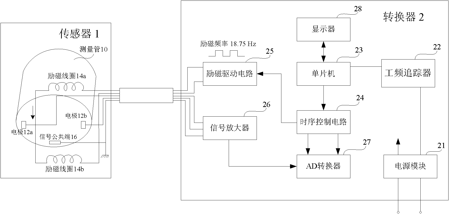
[0017] The inventors of the present invention found that, in the existing electromagnetic flowmeter, the existing problems include: the excitation frequency of the excitation current is limited to the even multiple frequency division of the power frequency, the interval between the excitation frequencies of adjacent two stages is relatively large, and there is very little room for selection. Small, resulting in the problem that the electromagnetic flowmeter cannot be well balanced between avoiding low-frequency noise interference and output stability.

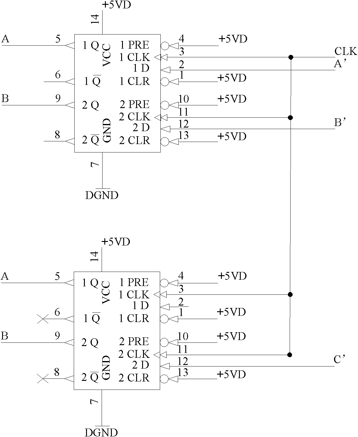
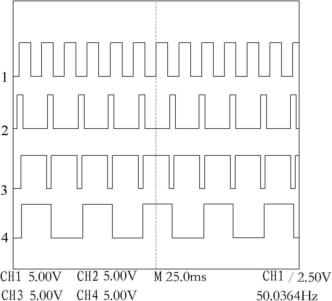
[0018] Therefore, the inventor of the present invention provides an electromagnetic flowmeter, which mainly expands the excitation frequency of the excitation current, breaking through the previous limitation that the excitation frequency is limited to even multiples of the power frequency, so that the excitation frequency is also It can be a non-even frequency division of the power frequency, and the interval between two adjace...


PUM


Abstract

The invention provides an electromagnetic flowmeter comprising a sensor and a converter, wherein the sensor comprises an exciting coil, an electrode and a conduit; the converter comprises an exciting drive circuit, a central processing unit and an electrode signal measurement unit; the exciting drive circuit produces an exciting current; and particularly, the exciting current has an exciting frequency of a fractional frequency which is an uneven number multiple of the power frequency. Compared with the prior art, the gap between two adjacent stages of exciting frequencies is small and the option is wide; and therefore, the minimization of low-frequency noise interference and the stable output both are taken into account.

Description

technical field [0001] The invention relates to the field of flow detection, in particular, to an electromagnetic flowmeter suitable for flow measurement of liquid containing slurry. Background technique [0002] The electromagnetic flowmeter applies a magnetic field to the measured fluid through the excitation coil, and the measured fluid moves in the magnetic field to induce an induced electromotive force, and the fluid flow velocity can be obtained by detecting and processing the electromotive force signal, thereby realizing flow measurement. At present, the excitation method is mainly low-frequency square wave excitation, that is, the excitation coil is powered by a constant current source, and the direction of the current in the excitation coil is constantly switched, so that the excitation current changes periodically between positive and negative constant values. During the constant excitation current, the output signal of the electromagnetic flow sensor can obtain a ...

Claims


Application Information

Patent Timeline
Patent Type & Authority Applications(China)
IPC IPC(8): G01F1/58
Inventor 李程生张振山汪小胖石明
Owner SHANGHAI WELLTECH AUTOMATION CO LTD
Why Eureka
Try Eureka