Disturbing force compensating control device

A technology of compensating control and disturbance force, applied in the field of disturbance force compensation control device, which can solve the problems that the friction force between movable parts has a large influence and cannot be fully grasped

Active Publication Date: 2012-09-05
FUJI KK +1
View PDF7 Cites 0 Cited by
  • Summary
  • Abstract
  • Description
  • Claims
  • Application Information

AI Technical Summary

Problems solved by technology

Furthermore, it is known that in order to make the positioning accuracy higher, the influence of the frictional force generated between the movable parts is large.
In addition, the disturbance force due to the influence of friction has nonlinear characteristics, and in the disturbance force based on the transfer characteristics described in Patent Document 1, it cannot be fully grasped.

Method used


Image

  • Disturbing force compensating control device
  • Disturbing force compensating control device
  • Disturbing force compensating control device

Examples


Embodiment Construction

[0080] Next, an embodiment of the disturbance force compensation control device according to the present invention will be described with reference to the drawings.

[0081] (1. Structure of this embodiment)

[0082] (1-1. Structure of mechanical device)

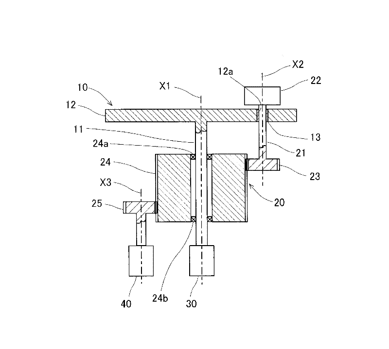
[0083] The disturbance force compensation control device of the present invention is a device for controlling a mechanical device described below. This mechanical device includes a plurality of movable parts and a plurality of actuators that drive the respective movable parts. Furthermore, this mechanical device has a structure in which a disturbing force acts on the operation of other movable parts due to the operation of each movable part. That is, when a certain movable part moves, this movement affects the movements of other movable parts.

[0084] As an example of this mechanism, such as figure 1 shown. For example, a head for picking up electronic parts in an electronic part mounter. Specifically, the mechanical ...


PUM


Abstract

The invention provides a disturbing force compensating control device, which can calculate disturbing force caused by friction force generated between movable parts in high precision, and perform high precision positioning via high precision disturbing estimation. A disturbing force model is set based on movable part friction force between sliding faces of the movable parts generated between a first movable part (10) and a second movable part (20) in a connection. Based on a first target position instruction value of a first actuator (30) driving the first movable part (10), a first referential thrust instruction value is calculated. Based on a second target position instruction value of a second actuator (40) driving the second movable part (20) and the disturbing force model, a first disturbing force generated by the action of the second movable part (20) acting upon the action of the first movable part (10) due to influence of friction force between the movable parts is calculated. Furthermore, through add of the first referential thrust instruction value and the first disturbing force, a first compensating thrust instruction value is calculated, and the first actuator (30) is controlled based on the first compensating thrust instruction value.

Description

technical field [0001] The present invention relates to a disturbance force compensating control device. In a mechanical device having a plurality of movable parts and a plurality of actuators driving each movable part, the action of one movable part interferes with the action of another movable part. When there is a force, the disturbance force compensation control device compensates the disturbance force to control the mechanical device. Background technique [0002] For example, in an electronic component mounting machine or the like, each movable part receives a disturbance force from other movable parts, which adversely affects positioning accuracy. Therefore, Japanese Patent No. 4241240 (Patent Document 1) describes that the disturbance force is calculated using the transfer characteristics from the sum of the thrusts of the movable parts (the reaction force transmitted from the chassis) to the position of the chassis. [0003] Patent Document 1: Japanese Patent No. 4...

Claims


Application Information

Patent Timeline
IPC IPC(8): G05D3/12G05B13/04
Inventor 饲沼谅藤田政利名桐启祐永田良城户隆志岩崎诚
Owner FUJI KK
Why Eureka
Try Eureka