Relative radiometric calibration method for light field camera

A technology of relative radiometric calibration and light field camera, applied in the field of relative radiometric calibration for light field cameras

Inactive Publication Date: 2012-09-12
ACAD OF OPTO ELECTRONICS CHINESE ACAD OF SCI
View PDF1 Cites 27 Cited by
  • Summary
  • Abstract
  • Description
  • Claims
  • Application Information

AI Technical Summary

Problems solved by technology

[0008] The purpose of the present invention is to provide a method for relative radiation calibration for light field cameras, which can eliminate the dark current noise of the light field camera system, remove invalid pixels between microlens sub-images, and correct errors caused by various factors. improve the performance of light field cameras

Method used


Image

  • Relative radiometric calibration method for light field camera
  • Relative radiometric calibration method for light field camera
  • Relative radiometric calibration method for light field camera

Examples


Embodiment Construction

[0035] The technical solutions in the embodiments of the present invention will be clearly and completely described below in conjunction with the accompanying drawings in the embodiments of the present invention. Obviously, the described embodiments are only some of the embodiments of the present invention, not all of them. Based on the embodiments of the present invention, all other embodiments obtained by persons of ordinary skill in the art without making creative efforts belong to the protection scope of the present invention.

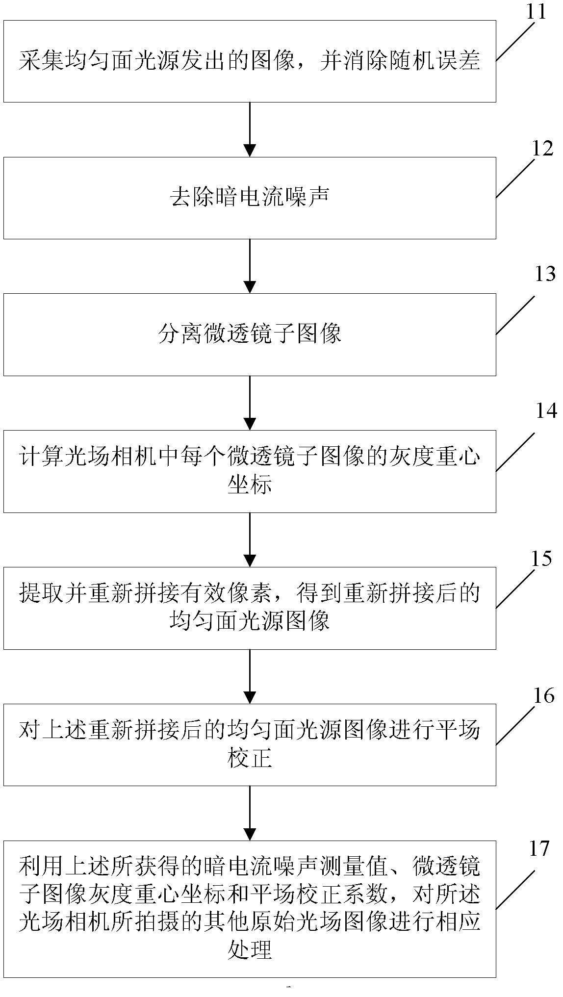
[0036] Embodiments of the present invention provide a method for relative radiation calibration of a light field camera. The embodiments of the present invention will be further described in detail below in conjunction with the accompanying drawings, as shown in figure 1 Shown is a schematic flow chart of the method provided by the embodiment of the present invention, and the method includes:

[0037] Step 11: Collect images from a uniform surface ...


PUM


Abstract

The embodiment of the invention discloses a relative radiometric calibration method for light field camera, which comprises the steps of: carrying out calibration processing of images emitted from an uniform area light source by a light field camera to obtain measurement values of dark current noise, grey centroid coordinates of subimages of microlens, and flat-field correction coefficients; and processing other original light field images shot by the light field camera correspondingly by utilizing the measurement values of dark current noise, the grey centroid coordinates of subimages of microlens, and the flat field correction coefficients to obtain light filed images after relative radiometric calibration processing. The method of the invention can eliminate dark current noise in light field camera system, remove invalid pixels between subimages of microlens, and correct the problem of pixel response nonuniformity caused by various factors, thereby improving the performance of the light field camera.

Description

technical field [0001] The invention relates to the technical field of light field imaging, in particular to a method for relative radiation calibration of a light field camera. Background technique [0002] Light field imaging technology is a new type of computational imaging technology, which combines traditional optical imaging technology with modern computer information processing technology, obtains four-dimensional light field information through optical modulation, and then uses information demodulation to process and obtain 2D images for different needs. This technology breaks through some inherent defects in traditional imaging technology, and has the characteristics of "photographing first and then focusing". The advantages. [0003] A light field camera generally consists of a main optical lens, a microlens array, and an image sensor. The microlens array is placed on the image plane of the main optical lens, and the image sensor is located on the back focal plan...

Claims


Application Information

Patent Timeline
Patent Type & Authority Applications(China)
IPC IPC(8): G06T7/00
Inventor 周志良袁艳相里斌吕群波苏丽娟
Owner ACAD OF OPTO ELECTRONICS CHINESE ACAD OF SCI
Why Eureka
Try Eureka