AI technical title is built by Patsnap AI team. It summarizes the technical point description of the patent document.
A technology of coupling device and connector
Active Publication Date: 2014-10-01
ANHUI TATFOOK TECH CO LTD
View PDF2 Cites 0 Cited by
Summary
Abstract
Description
Claims
Application Information
AI Technical Summary
This helps you quickly interpret patents by identifying the three key elements:
Problems solved by technology
Method used
Benefits of technology
Problems solved by technology
[0006] The present invention mainly solves the technical problems in the prior art that the PCB or the coupling components are easily damaged and the work efficiency is low due to the need to frequently dismantle and weld the PCB coupling components when adjusting the coupling and isolation, and provides a connector and its coupling
Method used
Image
Click on the blue label to locate the original text in one second.
Reading with bidirectional positioning of images and text.
Examples
Embodiment 1
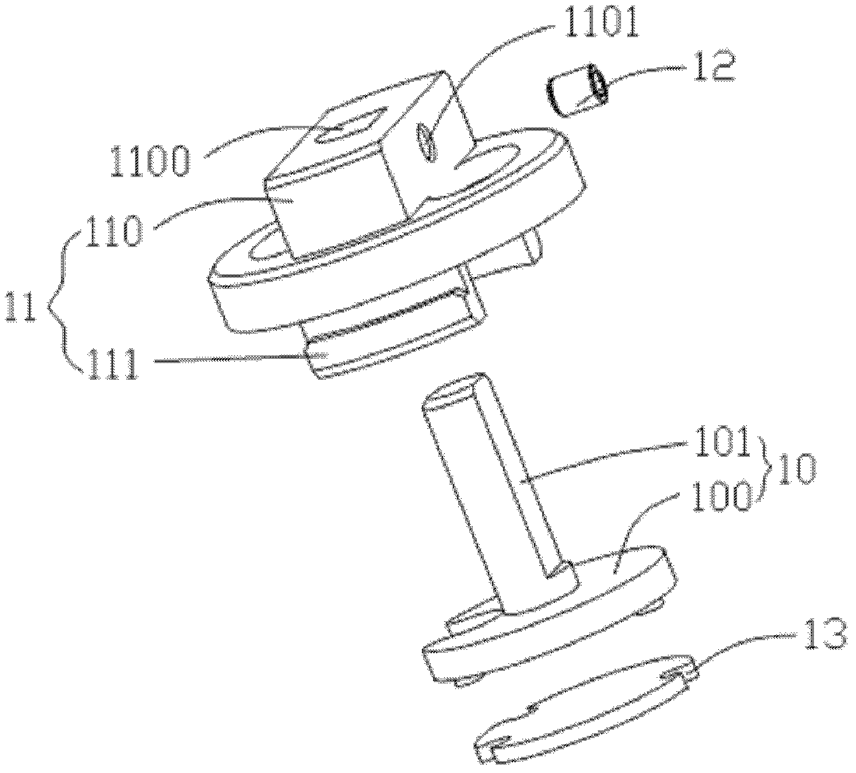
[0024] Embodiment 1, please refer to figure 1 , in this embodiment, the coupling device is applied but not limited to a connector, the connector includes a connecting rod connecting the input end and output end of the signal and an adjustment cavity provided in the connector, and the coupling device is arranged in the adjustment cavity; of course , the coupling device can also be used in other signal processing devices, which is not limited within the scope understood by those skilled in the art.
[0025] The coupling device includes, but is not limited to, an adjusting disc 10, a rotating bracket 11, and a tightening unit 12, wherein the adjusting disc 10 is a distance adjustment mechanism for adjusting the distance between the coupling circuit board 13 and the connecting rod; the rotating bracket 11 is an angle The adjustment mechanism is used to rotate the coupling circuit board 13 to change the angle between the coupling circuit board 13 and the axis direction of the conne...
Embodiment 2
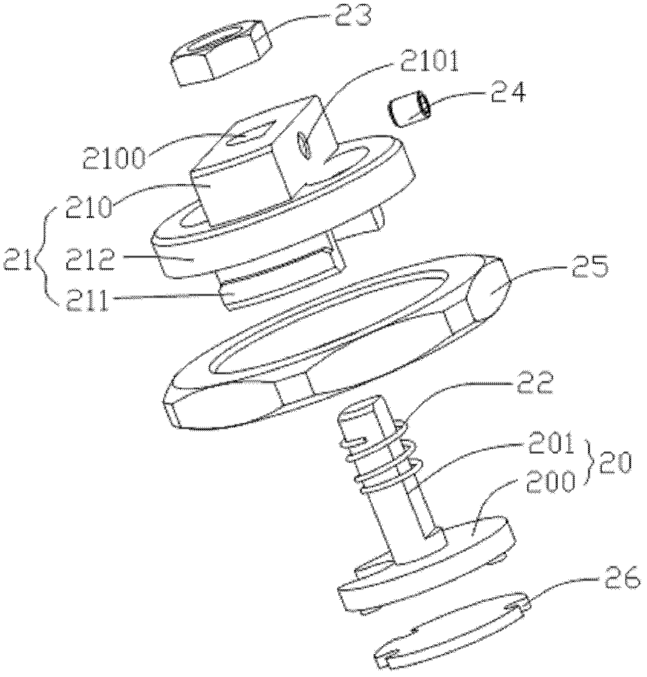
[0030] Embodiment two, please refer to Figure 2 to Figure 4 , the coupling device is used but not limited to a connector, the connector includes a connecting rod connecting the input end and the output end of the signal and an adjustment cavity arranged in the connector, and the coupling device is arranged in the adjustment cavity; of course, the coupling device can also be Use in other signal processing devices is not limited within the scope understood by those skilled in the art.
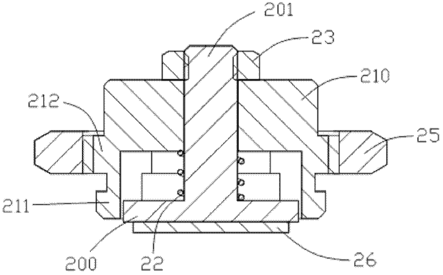
[0031] The coupling device includes but is not limited to an adjustment disc 20, a rotating bracket 21, an adjustment elastic body 22, an adjustment nut 23, a tightening unit 24 and a fastening nut 25, wherein the adjustment disc 10 is a distance adjustment mechanism for adjusting the coupling The distance between the circuit board 13 and the connecting rod; the rotating bracket 11 is an angle adjustment mechanism for rotating the coupling circuit board 13 to change the angle between the coupling ...
Embodiment 3
[0045] Embodiment 3. This embodiment provides a connector.
[0046] Please refer to Example 2 Figure 5 and Figure 6 , in this embodiment, the connector includes a connecting rod 30 connecting the input end and output end of the signal, an annular groove portion 31 and a plurality of limit portions 32, and the connector is also provided with a coupling device for configuring the aforementioned The adjustment cavity and the coupling circuit board 26 , as mentioned above, the coupling circuit board 26 is disposed on the surface of the base 200 adjacent to the connecting rod 30 .
[0047] In a preferred embodiment, the coupling circuit board 26 is provided with a microstrip circuit and a coupling element. Certainly, in other embodiments, the coupling plate and the coupling element can be arranged on the coupling circuit board 26 .
PUM
Abstract
The invention discloses a connector and a coupling device thereof. The connector comprises a connecting rod and an adjusting cavity, a signal input end is connected with a signal output end by the connecting rod, the adjusting cavity is arranged in the connector, the coupling device is disposed in the adjusting cavity and consists of a distance adjusting mechanism and an angle adjusting mechanism, the distance from a coupling circuit board to the connecting rod is adjusted by the distance adjusting mechanism, and the coupling circuit board is driven to rotate by the angle adjusting mechanism so that an included angle between the coupling circuit board and the axial direction of the connecting rod is changed. When the coupling degree and / or the isolation are adjusted, the connector and the coupling device thereof do not need to be frequently detached, welded and the like, the coupling circuit board and relevant devices are effectively protected, a debugging process is simple and speedy, and work efficiency is improved.
Description
technical field [0001] The invention relates to the field of signalprocessing, in particular to a connector and a coupling device thereof. Background technique [0002] In the prior art, the coupling device generally adopts a coupling plate or a microstrip (microstrip circuit). [0003] For example, in the way of using the coupling piece, a PCB (coupling circuit board) is set in the adjustment cavity of the connecting rod connecting the input end and the output end, and then the coupling piece and the coupling element are arranged on the PCB. When in use, by adjusting the coupling The coupling degree and isolation degree can be adjusted by changing the coupling element on the PCB and the chip. This method requires frequent replacement and welding of the coupling components, which is easy to cause damage to the PCB, the coupling piece or the coupling components, resulting in a waste of resources; and the coupling piece must be used alone, which cannot be integrated into the...
Claims
Application Information
Patent Timeline
Application Date:The date an application was filed.
Publication Date:The date a patent or application was officially published.
First Publication Date:The earliest publication date of a patent with the same application number.
Issue Date:Publication date of the patent grant document.
PCT Entry Date:The Entry date of PCT National Phase.
Estimated Expiry Date:The statutory expiry date of a patent right according to the Patent Law, and it is the longest term of protection that the patent right can achieve without the termination of the patent right due to other reasons(Term extension factor has been taken into account ).
Invalid Date:Actual expiry date is based on effective date or publication date of legal transaction data of invalid patent.

