Metamaterial-based directional coupler

A directional coupler and metamaterial technology, applied in the field of metamaterial-based directional couplers, can solve the problems of large insertion loss, small size, poor directivity, etc., and achieve improved directivity, reduced volume, and cost savings. Effect

Active Publication Date: 2013-03-06
KUANG CHI INST OF ADVANCED TECH +1
View PDF4 Cites 0 Cited by
  • Summary
  • Abstract
  • Description
  • Claims
  • Application Information

AI Technical Summary

Problems solved by technology

[0004] The purpose of the present invention is to overcome the defects in the prior art that the coupling degree of the coupler depends on the length of the coupling section, the directivity is not good, and the insertion loss is large, and provides a directional coupler based on metamaterials, the coupler has a directional High performance, good coupling flatness, large load capacity, multi-directional coupling, and small size for easy installation and use

Method used


Image

  • Metamaterial-based directional coupler
  • Metamaterial-based directional coupler
  • Metamaterial-based directional coupler

Examples


Embodiment 1

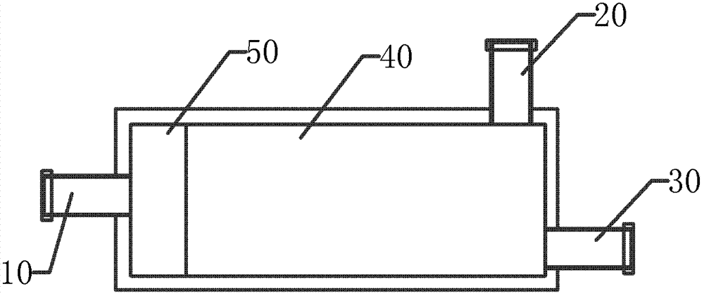
[0036] like figure 1 As shown, a metamaterial-based directional coupler, the directional coupler includes an input end 10, an output end 30, a coupling end 20, a matching module 50 and a coupling module 40, wherein the input end 10 and the One end of the matching module 50 is connected; the coupling module 40 is connected with the output terminal 30 and the coupling terminal 20 respectively; The input enters the matching module 50 and then enters the coupling module 40 , a part of the electromagnetic wave signal is directly output from the output terminal 30 , and another part of the electromagnetic wave signal is coupled to the coupling terminal 20 through the coupling module 40 and then output.

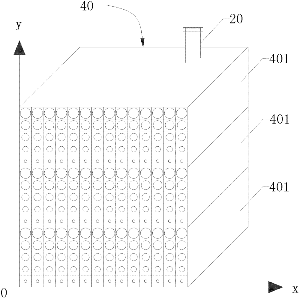
[0037] like figure 2 As shown, the coupling module 40 includes a plurality of metamaterial panels 401, and the plurality of metamaterial panels 401 are identical and have the same refractive index distribution law, that is, when the electromagnetic wave signal passes through the c...

Embodiment 2

[0053] like Figure 8 As shown, a metamaterial directional coupler includes an input terminal 10', a coupling module 40', a first coupling terminal 201, a second coupling terminal 202 and an output terminal 30'. After the electromagnetic wave signal enters the coupling module 40' from the input terminal 10', a part of the electromagnetic wave signal is directly transmitted from the output terminal 30', and a part of the electromagnetic wave signal is coupled through the coupling module 40' and then enters the first coupling terminal 201 and the second coupling terminal 201. Terminal 202. The main difference between this embodiment and Embodiment 1 is that the coupling module 40' is relatively connected together by two metamaterial panels with the same refractive index distribution, such as Figure 9 As shown, the electromagnetic wave has coupling in two directions. The oppositely connected metamaterial panels may also have different refractive indices, which depends on pract...


PUM

PropertyMeasurementUnit
Thicknessaaaaaaaaaa

Abstract

The invention relates to the field of radio frequency and microwave signal transmission and provides a metamaterial-based directional coupler. The directional coupler comprises an input end, an output end, a coupling end, a coupling module and a matching module, wherein the input end is connected with one end of the matching module; the coupling module is connected with the output end and the coupling end respectively; and the other end of the matching module is connected with the coupling module. The directional coupler has the beneficial effects that the directional coupler adopts the metamaterial technology, and by changing refractive index distribution inside the metamaterial, the directional coupler has the characteristics of high directionality, good coupling flatness, high loading power, capability of achieving multidirectional coupling, small volume and convenience in installation and use.

Description

technical field [0001] The invention relates to the technical field of radio frequency and microwave signal transmission, and more specifically relates to a directional coupler based on metamaterials. Background technique [0002] The directional coupler is a general-purpose microwave or millimeter-wave component, which can be used for signal isolation, separation and mixing, such as power monitoring, source output power stabilization, signal source isolation, frequency sweep testing of transmission and reflection, etc. A high-performance directional coupler requires small size, low loss to the transmission signal, good flatness and directivity of the coupled signal, good coupling degree and standing wave ratio, and sufficient power capacity. [0003] Most of the existing directional couplers are microstrip couplers. Because the microstrip directional couplers are coupled by the narrow side of the main and auxiliary microstrip lines, the coupling is very weak, and the coupli...

Claims


Application Information

Patent Timeline
IPC IPC(8): H01P5/18
Inventor 刘若鹏季春霖岳玉涛黄沣
Owner KUANG CHI INST OF ADVANCED TECH
Why Eureka
Try Eureka