
Coupler, debugging circuit thereof and communication equipment

A technology for debugging circuits and couplers, applied in the field of communications, can solve problems such as reducing the directionality and consistency of couplers, and achieve the effects of convenient debugging, saving human resources and improving efficiency

Pending Publication Date: 2022-02-08
ANHUI TATFOOK TECH CO LTD
View PDF0 Cites 0 Cited by
  • Summary
  • Abstract
  • Description
  • Claims
  • Application Information

AI Technical Summary

Problems solved by technology

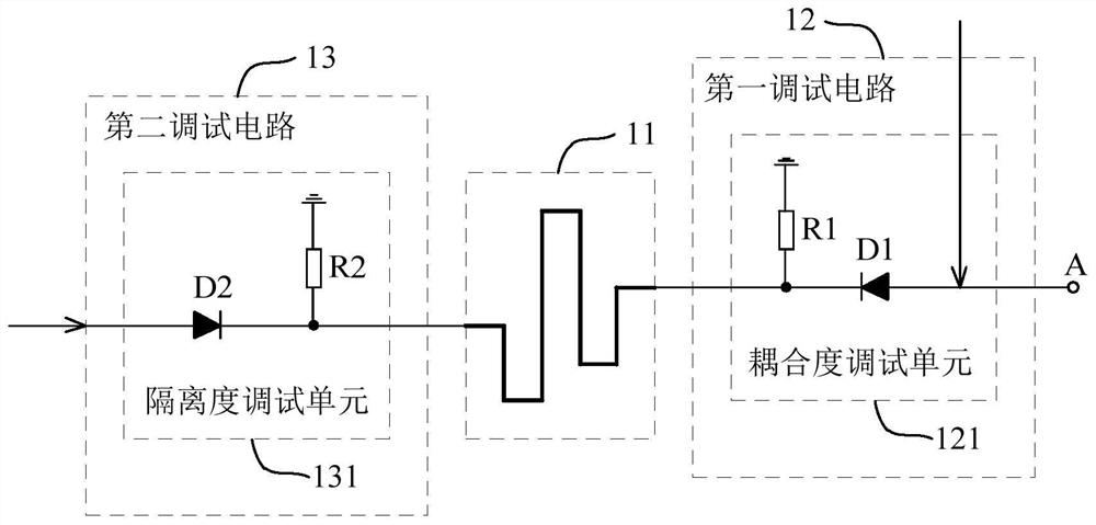
[0004] In view of this, the embodiment of the present application provides a coupler and its debugging circuit, and communication equipment to solve the technical problem that the existing coupler index debugging method will reduce the directionality and consistency of the coupler

Method used


Image

  • Coupler, debugging circuit thereof and communication equipment
  • Coupler, debugging circuit thereof and communication equipment
  • Coupler, debugging circuit thereof and communication equipment

Examples


Embodiment Construction

[0018] In order to make the purpose, technical solution and advantages of the present application clearer, the present application will be further described in detail below in conjunction with the accompanying drawings and embodiments. It should be understood that the specific embodiments described here are only used to explain the present application, and are not intended to limit the present application.

[0019] It should be noted that the terms used in the implementation manners of the embodiments of the present application are only used to explain the specific embodiments of the present application, and are not intended to limit the present application. In the description of the embodiments of the present application, unless otherwise specified, " / " means or means, for example, A / B can mean A or B; "and / or" in this article is only a description of associations A relationship means that there may be three kinds of relationships, for example, A and / or B means: A exists alon...


PUM


Abstract

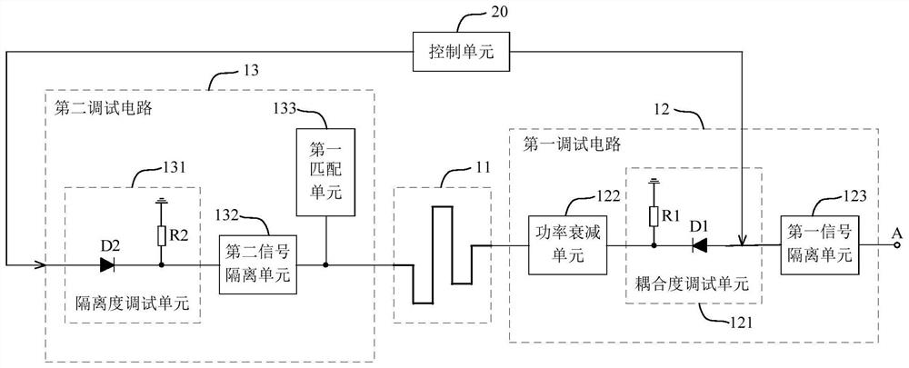
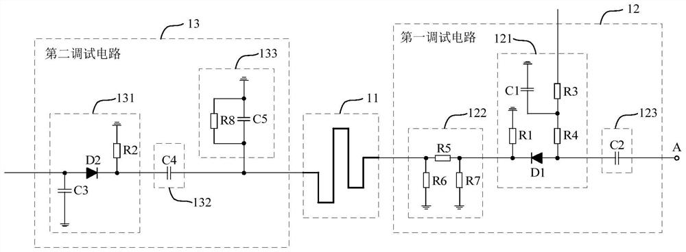
The invention is suitable for the technical field of communication, and provides a coupler, a debugging circuit thereof and communication equipment. The debugging circuit comprises a first debugging circuit and a second debugging circuit. A coupling degree debugging unit comprising a first PIN diode and a first resistor is arranged in the first debugging circuit, the anode of the first PIN diode receives a first direct-current electric signal, and the first direct-current electric signal reaches the ground after flowing through the first PIN diode and the first resistor. The equivalent impedance of the first PIN diode changes along with the change of the forward bias current of the first PIN diode. An isolation debugging unit comprising a second PIN diode and a second resistor is arranged in the second debugging circuit, the anode of the second PIN diode receives a second direct-current electric signal, and the second direct-current electric signal reaches the ground after flowing through the second PIN diode and the second resistor. The equivalent impedance of the second PIN diode changes along with the change of the forward bias current of the second PIN diode. Therefore, manual debugging is not needed, and the directivity and consistency of the coupler are improved.

Description

technical field [0001] The application belongs to the technical field of communication, and in particular relates to a coupler, a debugging circuit thereof, and a communication device. Background technique [0002] A directional coupler is a directional power coupling element that can be used for signal isolation, separation or mixing, etc. As an important part of microwave / RF circuits, it has been widely used in various communication systems. The technical indicators of the coupler usually include: coupling degree, isolation degree and directivity, etc. In order for the coupler to meet the actual application requirements, it is usually necessary to debug various indicators of the coupler. [0003] In the prior art, a mechanical adjustable potentiometer is usually installed at the coupling end or isolation end of the coupler, and the resistance value of the potentiometer is changed by adjusting the position of the potentiometer, thereby realizing the adjustment of various i...

Claims


Application Information

Patent Timeline
Patent Type & Authority Applications(China)
IPC IPC(8): H01P5/18
CPCH01P5/18
Inventor 严尚格
Owner ANHUI TATFOOK TECH CO LTD
Learn More