Eureka AIR delivers breakthrough ideas for toughest innovation challenges, trusted by R&D personnel around the world.

Vehicle seat

A seat and passenger technology, applied in the direction of the seat frame, vehicle seat, special position of the vehicle, etc., can solve the problems that the load cannot be fully reduced, and it is difficult to prevent the rear of the head from moving, and achieve simple structure, light structure, The effect of reducing the load

Inactive Publication Date: 2012-09-12
TS TECH CO LTD
View PDF9 Cites 2 Cited by
  • Summary
  • Abstract
  • Description
  • Claims
  • Application Information

AI Technical Summary

Problems solved by technology

[0004] However, with only fixed head restraints, it is difficult to prevent the head from moving sharply rearward in a rear collision
In the event of a rear collision, if the distance between the occupant's head and the headrest is not quickly reduced to support the head, the head will move backward rapidly, and the load on the neck may not be sufficiently reduced

Method used


Image

  • Vehicle seat
  • Vehicle seat
  • Vehicle seat

Examples


no. 1 example

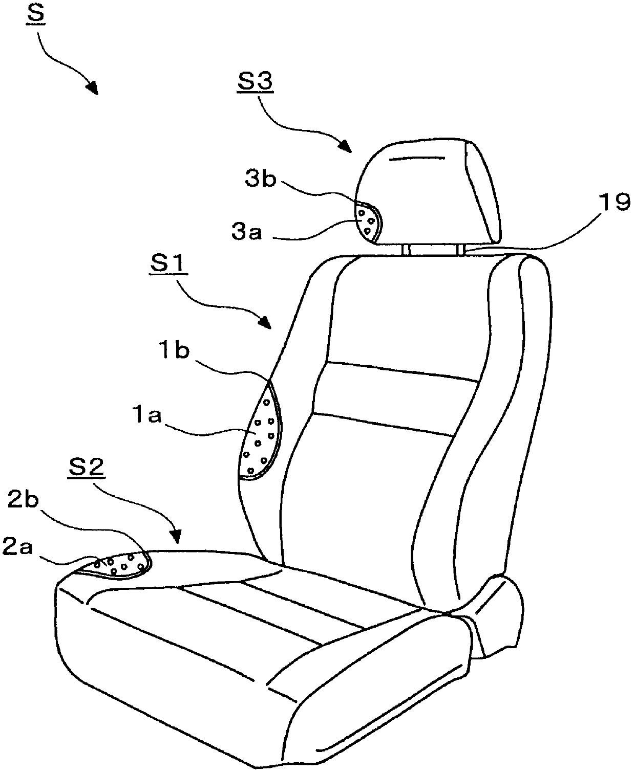
[0094] Such as figure 1 As shown, the vehicle seat S according to the first embodiment is composed of a seat back S1 (back), a seat portion S2, and a headrest S3. The seat back S1 (back) and the seat portion S2 have cushion pads 1a, 2a mounted on the seat frame F, and cover skin materials 1b, 2b. Therefore, the below-mentioned waist entry blocking member 25 also has a structure in which the cushion pad 1a is mounted and the skin material 1b is covered. In addition, the headrest S3 is formed by providing the cushioning material 3a on the headrest pillar 19 and covering the skin material 3b.

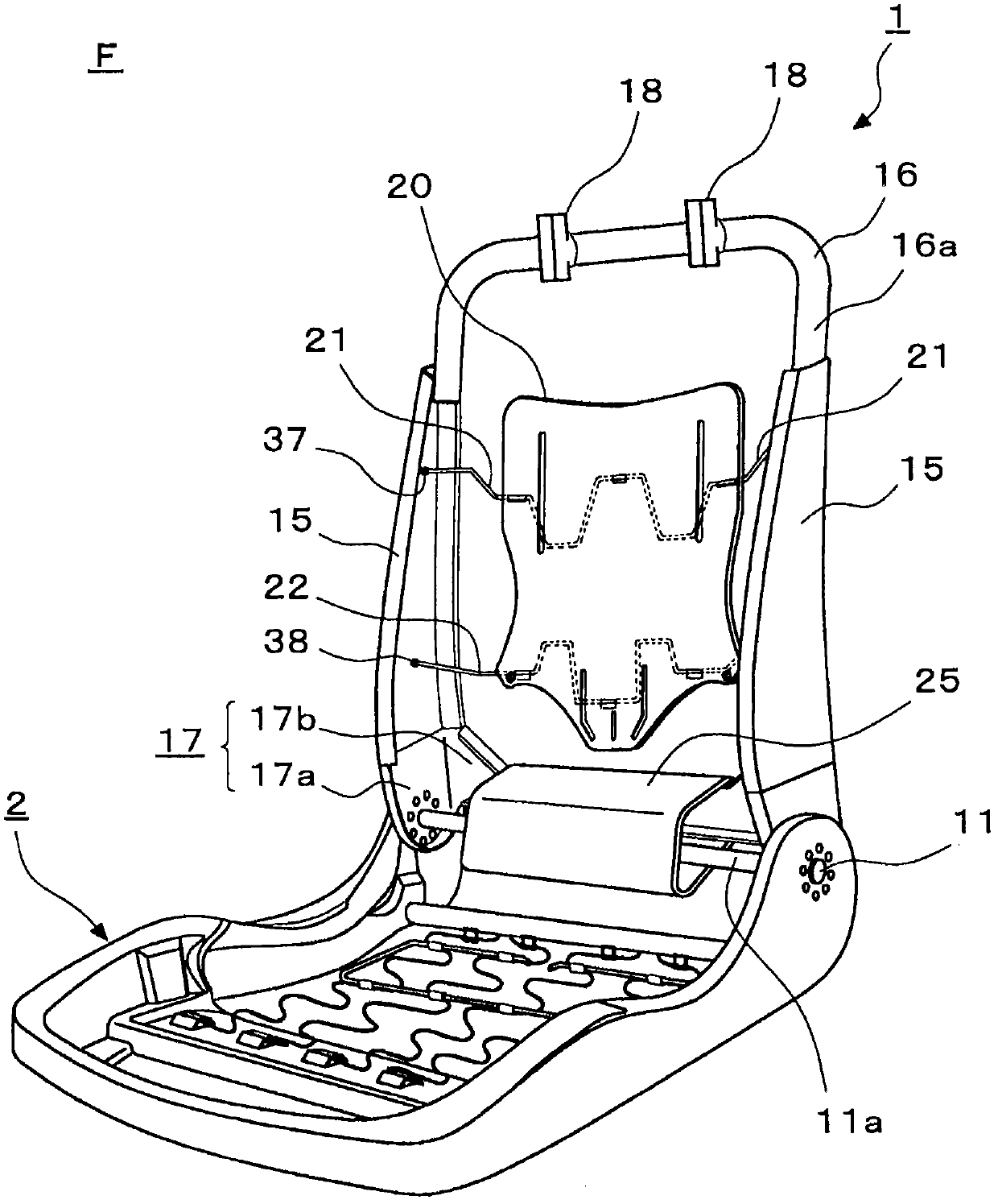
[0095] Such as figure 2 As shown, the seat frame F of the vehicle seat S is composed of a seat back frame 1 constituting a seat back S1 and a seat frame 2 constituting a seat portion S2.

[0096] As described above, the cushion pad 2a is mounted on the seat frame 2, and the surface material 2b is covered from the top of the cushion pad 2a to support the occupant from below. The seat f...

no. 2 example

[0136] pass below Figure 6 to Figure 8 The method of joining the waist-entrance preventing member 26 and the lower frame 17 and the structure of the waist-entrance preventing member 26 in the second embodiment will be described in detail. Image 6 It is a brief perspective view of the part 26 that hinders the entry of the waist, Figure 7 is a simplified perspective view of the seat back frame, Figure 8 It is an explanatory drawing of the side frame and the part that prevents the entry of the waist.

[0137] The waist entry blocking member 26 of the second embodiment is different from the waist entry blocking member 25 of the first embodiment in which a part of the rear face is a cutout, and is characterized by a rear face 26g. In addition, since the structure and function of the waist entry preventing member 26 other than the method of attaching to the lower frame 17 are the same as those of the waist entry preventing member 25 of the first embodiment, description thereof...

no. 3 example

[0153] The following is based on Figure 9 The structure of the waist entry preventing member 27 of the third embodiment will be described in detail. Figure 9 is a simplified perspective view of the seat back frame.

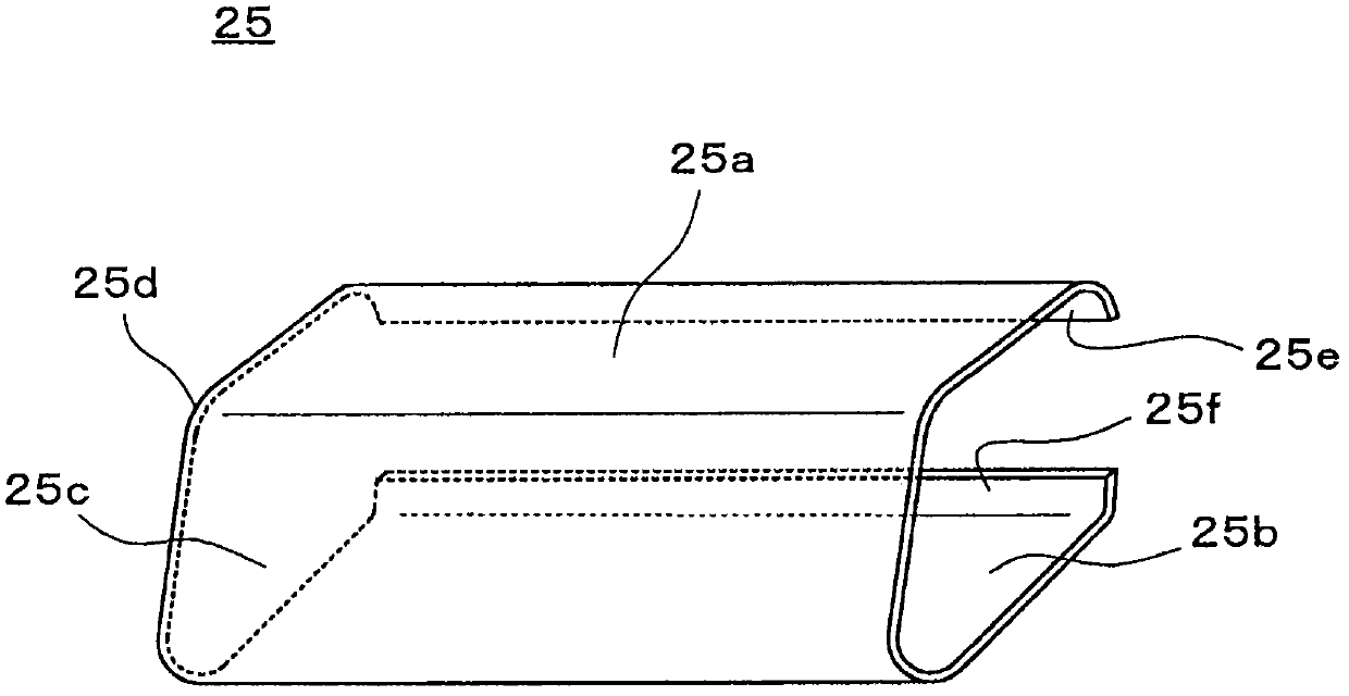
[0154] The waist entry hindering part 27 involved in the third embodiment is different from the waist entering hindering part 25 of the first embodiment, which is formed by plates connected by the upper face 25a, the lower face 25b, and the front face 25c. 27b, the front face 27c is formed separately in the central part. In addition, since the structure and function other than the separation of the waist-entrance preventing member 27 are the same as those of the waist-entrance preventing member 25 of the first embodiment, description thereof will be omitted.

[0155] In the third embodiment, such as Figure 9 As shown, the lumbar entry barrier 27 has an escape in a substantially central portion. The escaping portion is designed so that there is no plate mate...


PUM


Abstract

PROBLEM TO BE SOLVED: To provide a vehicle seat in a simple constitution, which effectively reduces the load on the neck or the like of an occupant by preventing any sink of a waist of the occupant with respect to a seat back to guide the backward turn of the entire upper body in a rear end collision, and reduces the degree that the neck of the occupant is independently tilted backwardly. ; SOLUTION: The vehicle seat S has a neck load reducing means 25 which increases the backward movement of the connection point between the neck and the body portion in comparison with the backward movement below the body portion of an occupant in a rear end collision, and sinks an upper body portion in a seat back S1.

Description

technical field [0001] The present invention relates to a vehicle seat, and more particularly to a vehicle seat capable of reducing the load on a passenger during a rear collision. Background technique [0002] When the rear portion of a passenger vehicle such as a car is rear-ended or is hit while traveling in reverse, that is, in a rear collision, a huge load may be applied to the neck (neck) of the passenger. Generally, the main reason for receiving such a load is that the neck is excessively bent and stretched due to only the head moving sharply rearward with respect to the chest of the seated passenger. That is, during a rear collision, the head of the seated occupant rapidly tilts backward due to inertial force, and a load is applied to the neck. [0003] Therefore, in the passenger seats of current automobiles and the like, in order to protect the passenger's head or neck from the impact caused by the rear collision and reduce the load on the neck, a seat is provided...

Claims


Application Information

Patent Timeline
IPC IPC(8): B60N2/42B60N2/90
CPCB60N2/4228B60N2/42745B60N2/42781B60N2/68B60N2/888
Inventor 新妻健一古田将也
Owner TS TECH CO LTD
Why Eureka
Eureka Blog
Learn More