
Multi-operation-mode modular continuum robot

A modular and continuum technology, applied in the field of robotics, can solve the problems that the robot can only be used as a mechanical arm, the user cannot independently modularize the assembly, and the drive components are bulky, etc., to achieve light structure, simple structure, and good stability Effect

Active Publication Date: 2022-02-08
SHANGHAI UNIV
View PDF12 Cites 0 Cited by
  • Summary
  • Abstract
  • Description
  • Claims
  • Application Information

AI Technical Summary

Problems solved by technology

[0004] Aiming at the deficiencies in the above-mentioned prior art, the present invention proposes a modular continuum robot with multi-operation modes, which solves the difficulty in controlling the drive of the current continuum robot, the large volume of the drive components, and the inability of the user to independently modularize the assembly. Robots and the problem of only being able to function as a robotic arm

Method used


Image

  • Multi-operation-mode modular continuum robot
  • Multi-operation-mode modular continuum robot
  • Multi-operation-mode modular continuum robot

Examples


Embodiment 1

[0037] Embodiment 1 The continuum robot is used as a mobile robot (a section of the torso assembly)

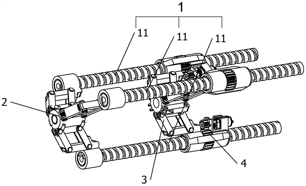
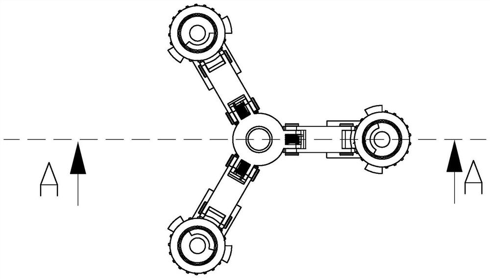
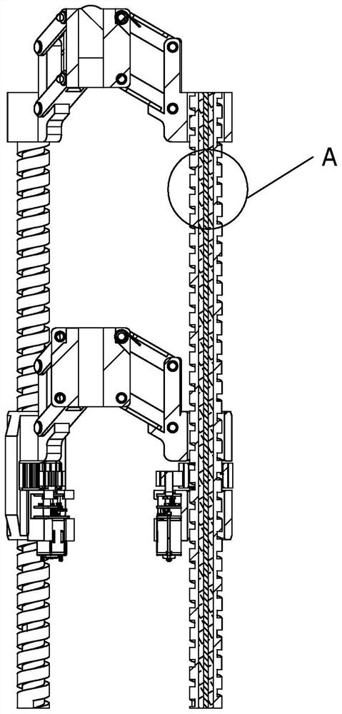
[0038] Such as Figure 1-5 As shown, the present invention includes a first base 2, a second base 3, a trunk assembly 1 and a drive assembly 4, the first base 2 includes a first connecting cylinder 21, three four-bar structures one 22 and three first fixed terminals 23 , the three four-bar structures 22 are evenly spaced and fixed on the circumferential surface of the first connecting cylinder 21 .

[0039] Flexible screw rod 11 comprises hollow bellows 111, foam interlayer pipe 112 and glass fiber rod 113, and foam interlayer pipe 112 is arranged in the chamber of hollow bellows 111, and glass fiber rod 113 is arranged in the chamber of foam interlayer pipe 112, and foam interlayer pipe The outer diameter of 112 is equal to the inner diameter of the hollow bellows 111, the outer diameter of the glass fiber rod 113 is equal to the inner diameter of the foam interlayer tube 11...

Embodiment 2

[0047] Embodiment 2 The continuum robot is used as a mobile robot (two-section torso assembly)

[0048] Such as Figure 9 As shown, the difference from Embodiment 1 is that the present invention includes a first base 2, two second bases 3, two trunk assemblies 1 and two drive assemblies 4, and the front end of the previous trunk assembly 1 is fixed A first base 2, a second base 3 is used to connect the two trunk assemblies 1, the previous trunk assembly 1 can move in the second base 3, and the front end of the latter trunk assembly 1 is connected to the second base 3. The second base 3 is fixed, and the rear trunk assembly 1 is connected with another second base 3 and can move in the second base 3 .

[0049] Such as Figure 10 and Figure 11 , the second base 3 includes a second connection cylinder 31, six four-bar structures two 32, three drive terminals 33 and three second fixed terminals 34, and the six four-bar structures two 32 are evenly fixed on the second The perip...

Embodiment 3

[0054] Embodiment 3 The continuum robot is used as a mechanical arm (two-section trunk assembly)

[0055] Such as Figure 9 and Figure 16 As shown, the difference between this embodiment and embodiment 2 is that the second base 3 at the end can be fixed on the connecting frame 6 when the present embodiment is used, and the present invention can be installed on the connecting frame by means of hoisting. 6, add an adsorption device at the front end of the first base 2, such as an electromagnet, a mechanical claw or a vacuum chuck 5, to realize the grasping of objects.


PUM


Abstract

The invention provides a multi-operation-mode modular continuum robot which comprises at least one trunk assembly, at least one first base, at least one second base and at least one driving assembly. The front end of the trunk assembly is fixed to the first base. The trunk assemblies can horizontally move in the second bases in the axis direction of the trunk assemblies, the driving assemblies are arranged on the second bases, the trunk assemblies can move in the second bases, and the other trunk assembly can be additionally installed behind each second base. The two sections of trunk assemblies are spliced together through one second base, the axial directions of all the spliced trunk assemblies are consistent, and each section of trunk assembly comprises three flexible screw rods. The driving assembly is simple in structure and accurate in control, a user can autonomously conduct modular assembly, and the assembly efficiency is improved. The mechanical arm is matched with various auxiliary operation tools to serve as a mechanical arm or a mobile robot.

Description

technical field [0001] The invention belongs to the technical field of robots, and in particular relates to a multi-operation mode modular continuum robot. Background technique [0002] Traditional industrial robots have increasingly replaced human repetitive labor, and achieved good results. However, with the in-depth application of robots in various fields, higher requirements are placed on robot operations in some applications in the manufacturing and social service fields. Traditional rigid robots are installed on At the joints of the robot, the overall mechanism is bulky, and the connecting rod is a rigid structure, which poses a potential threat to human safety. In addition, the robot body is rigid and difficult to achieve compliant control, which makes it unable to adapt to the environment well. The continuum robot with essential flexibility, light structure and high flexibility can well make up for the shortcomings of existing industrial robots and expand the appli...

Claims


Application Information

Patent Timeline
Patent Type & Authority Applications(China)
IPC IPC(8): B25J11/00
CPCB25J11/00
Inventor 王明远袁建军杜亮马书根鲍晟贾文川周锦书
Owner SHANGHAI UNIV
Learn More