A CT machine and its rotating body

A technology of rotating body and rotating matrix, which is used in medical science, diagnosis, computed tomography scanners, etc., can solve the problems of unsuitable high-speed rotating scanning and easy deformation of rotating bodies, and achieve high-speed rotating scanning, suppress deformation, and improve the overall The effect of stiffness

Active Publication Date: 2021-03-16
BEIJING NEUSOFT MEDICAL EQUIP CO LTD
View PDF8 Cites 0 Cited by
  • Summary
  • Abstract
  • Description
  • Claims
  • Application Information

AI Technical Summary

Problems solved by technology

[0013] Therefore, it is urgent to design a CT machine and its rotating body to solve the problem that the rotating body is easily deformed and not suitable for high-speed rotating scanning.

Method used


Image

  • A CT machine and its rotating body
  • A CT machine and its rotating body
  • A CT machine and its rotating body

Examples


Embodiment Construction

[0040] The invention provides a CT machine and its rotating body, which can suppress the deformation of the rotating body, improve the overall rigidity of the rotating body, meet the needs of high-speed rotating scanning, and realize the purpose of simplifying the structure and reducing weight .

[0041] The present invention will be described in detail below in conjunction with the accompanying drawings, so that those skilled in the art can accurately understand the technical solution of the present invention.

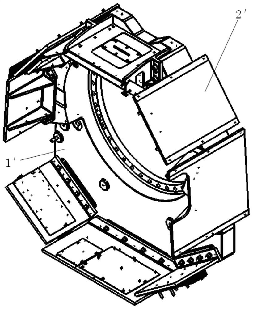
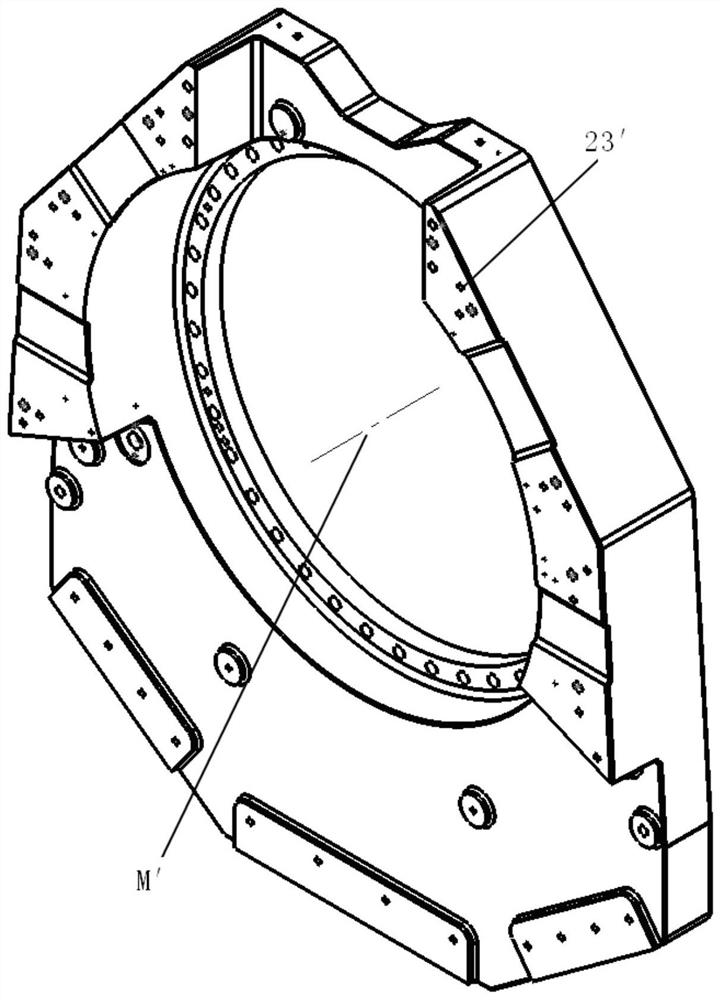
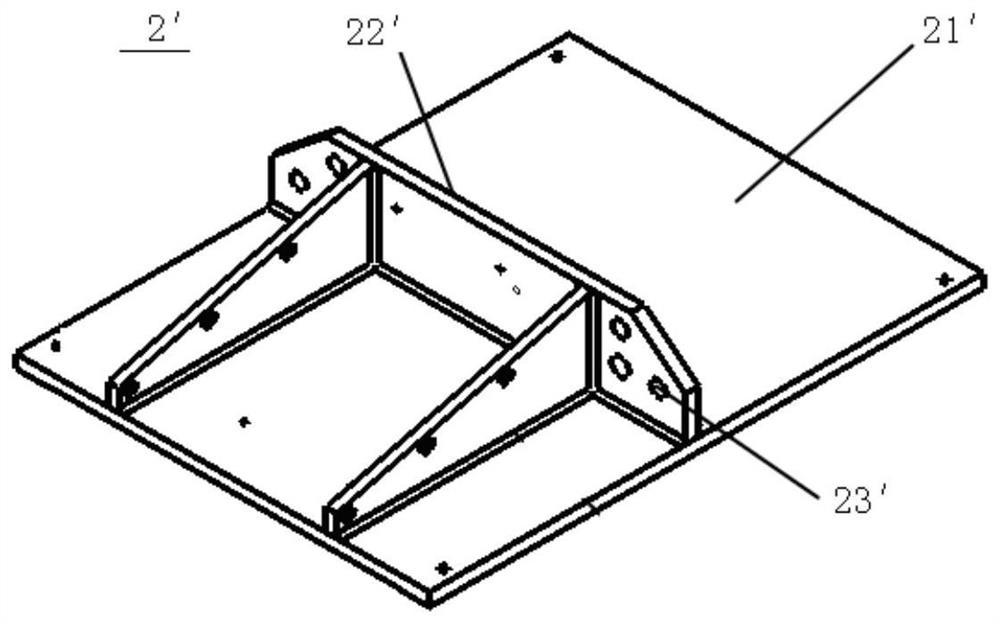
[0042] Such as Figure 5As shown, the present invention provides a rotating body of a CT machine, comprising a rotating base 1, a carrier 3 and a reinforcement 2, the rotating base 1 constitutes the basis of the rotating body, and has a scanning hole 11 for the CT machine to scan the human body; 3 is used to carry the scanning components, that is, the components required for scanning, such as ball tubes, detectors and high-voltage electrical components, etc., the bea...


PUM


Abstract

A Computed Tomography (CT) machine and a rotator thereof are provided. The rotator includes a rotating base with a scanning hole, a reinforcement with an axial through hole, and a load-carrying part for carrying scanning parts. The reinforcement is of a circumferentially closed structure. The axial through hole communicates with the scanning hole in a way that the reinforcement does not axially block the scanning hole. The load-carrying part is mounted on an external peripheral surface of the rotating base, and an axial end of the load-carrying part is connected with the reinforcement.

Description

technical field [0001] The invention relates to the technical field of CT systems, in particular to a CT machine and its rotating body. Background technique [0002] A modern CT (Computed Tomography) system is basically composed of a scanning table system that carries a patient, and a scanning gantry system that carries components such as tubes, high voltage and detector systems and rotates around the human body for scanning. Among them, the tubes, The high voltage and detector system are carried by the rotating body, and connected through the rotating body to form the rotating system of CT. [0003] Please refer to Figure 1-Figure 4 , figure 1 It is a schematic structural diagram of a typical rotating body in the prior art; figure 2 for figure 1 Schematic diagram of the structure of the matrix in the rotating body shown; image 3 for figure 1 Schematic diagram of the structure of the bracket in the rotating body shown; Figure 4 It is a structural schematic diagr...

Claims


Application Information

Patent Timeline
Patent Type & Authority Patents(China)
IPC IPC(8): A61B6/03
CPCA61B6/032A61B6/035A61B6/4435A61B6/08A61B6/44
Inventor 于军
Owner BEIJING NEUSOFT MEDICAL EQUIP CO LTD
Why Eureka
Try Eureka