Low visibility landing system and method

A technology of a landing system and an instrument landing system, applied in the field of landing systems, can solve problems such as inability to perform CATII or III landings

Active Publication Date: 2012-09-12
GULFSTREAM AEROSPACE CORP
View PDF4 Cites 18 Cited by
  • Summary
  • Abstract
  • Description
  • Claims
  • Application Information

AI Technical Summary

Problems solved by technology

Currently, WAAS is only suitable for CAT I landings and cannot currently be performed by CAT II or III landings

Method used


Image

  • Low visibility landing system and method
  • Low visibility landing system and method
  • Low visibility landing system and method

Examples


Embodiment Construction
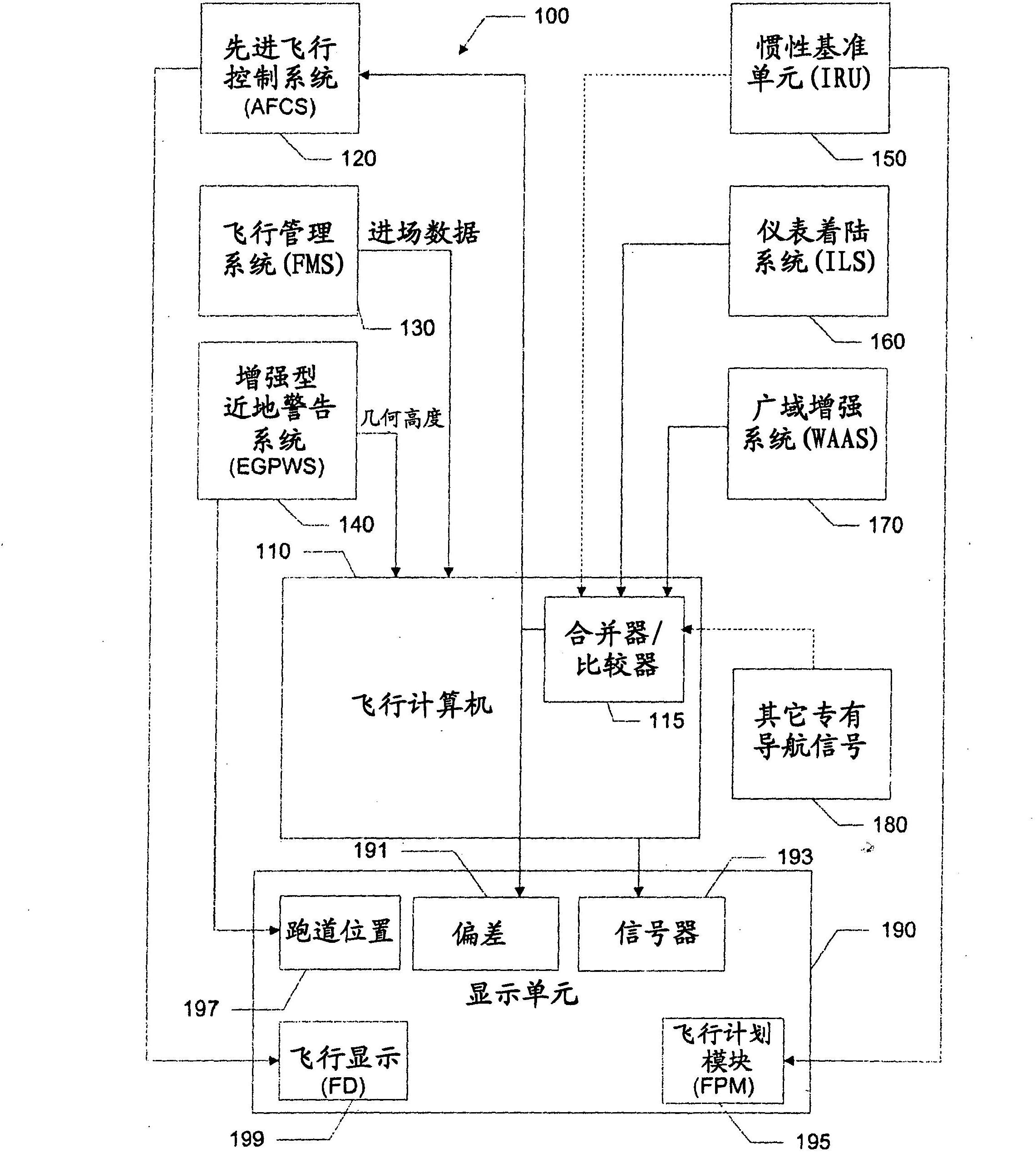
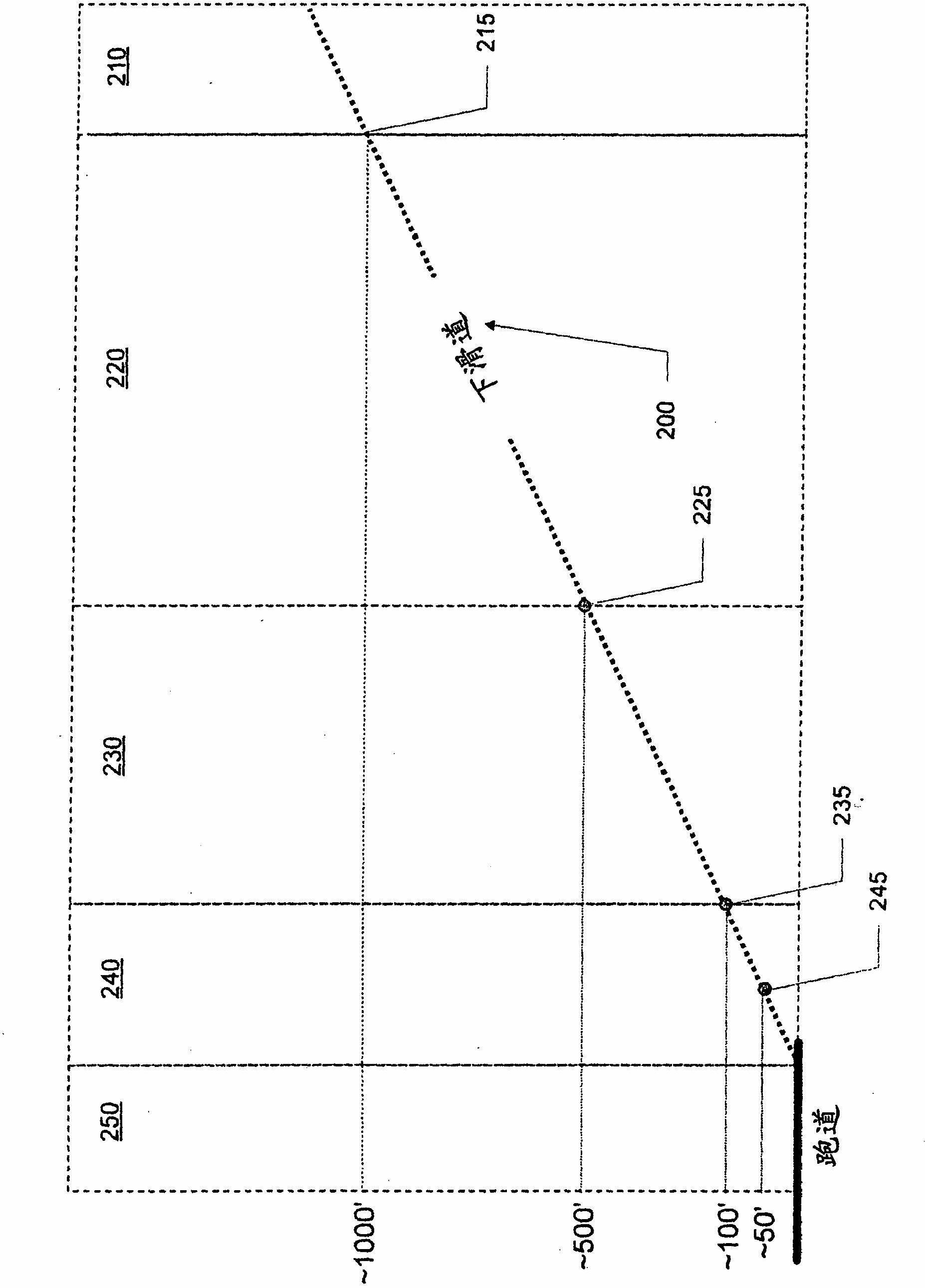
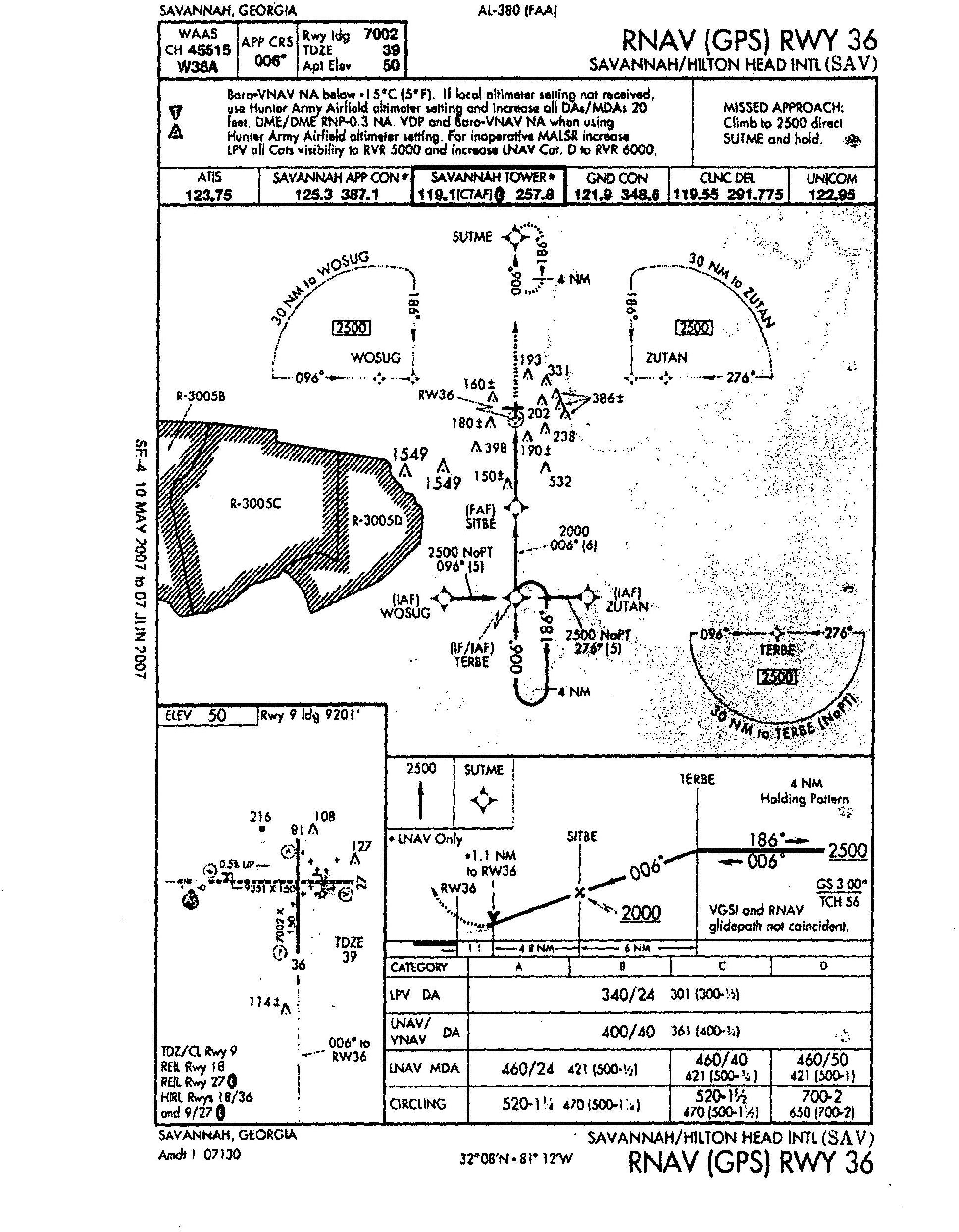
[0025] CAT I, CAT II, ​​and CAT III landing approaches utilize high-precision landing systems that employ various ground-based, space-based, and airborne equipment to assist in landing the aircraft. In at least one embodiment of the invention, the low visibility landing system can be configured so that aircraft landing approaches can be made to lower altitudes (in terms of decision height (DH)), and closer distances (in terms of runway Visual range (RVR) before). In some cases, embodiments of the present invention may utilize equipment configured for CAT I landings and use the equipment to conduct landing procedures with lower DH and RVR than would be possible under conventional CAT I landing procedures.

[0026]In some embodiments of the invention, the low visibility landing system may be configured to generate a composite signal from the separate signals of the two landing systems. For example, the landing system can utilize signals from the instrument landing system (ILS) ...


PUM


Abstract

Examples of the present invention may include a low visibility landing system for guiding aircraft on landing approaches. The low visibility landing system may aid a pilot during landing in low visibility conditions such that an aircraft may descend to lower altitudes without visual contact with the runway than is possible with other landing systems. The system may use various navigational systems to produce a hybrid signal that may be more stable than individual signals of those navigational systems. The hybrid signal is compared to a predetermined landing approach plan to determine the deviation of the aircraft from the landing approach plan and to provide guidance to the pilot to get the aircraft back onto the landing approach plan.; The system may also use multiple navigational systems to perform checks on an operation of a primary navigational system to ensure that the primary navigational system is operating accurately.

Description

technical field [0001] Embodiments of the present invention relate to aircraft landing systems, and more particularly, to landing systems for use in low visibility conditions. Background technique [0002] Commercial aircraft currently employ guidance systems that warn pilots when the plane is off course. Guidance systems must have a certain level of accuracy, integrity, continuity and availability during normal flight. Guidance systems for landing require additional levels of accuracy, integrity, continuity and availability. Landing systems typically provide high-precision data relating to the aircraft's position and deviation from the landing approach path. Such high precision often requires special equipment useful in situations where fog, clouds, and / or other conditions reduce visibility. [0003] The Federal Aviation Administration (FAA) or other certifying agencies classify aircraft landing systems into different categories (Category I, II and III) based on the leve...

Claims


Application Information

Patent Timeline
Patent Type & Authority Applications(China)
IPC IPC(8): B64D45/04G08G5/02G01C21/00
CPCG05D1/0676G08G5/025
Inventor R·S·塔卡克斯G·M·弗里曼
Owner GULFSTREAM AEROSPACE CORP
Why Eureka
Try Eureka