Drive belts for transmissions with convex pulley pulleys

A transmission belt and continuously variable transmission technology, applied in the field of transmission belts, can solve problems such as unbalanced distribution

Active Publication Date: 2015-11-25
ROBERT BOSCH GMBH
View PDF7 Cites 0 Cited by
  • Summary
  • Abstract
  • Description
  • Claims
  • Application Information

AI Technical Summary

Problems solved by technology

Such wear is found to be problematic in particular if it is distributed unevenly so that the convex profile of the side surfaces changes during operation

Method used


Image

  • Drive belts for transmissions with convex pulley pulleys
  • Drive belts for transmissions with convex pulley pulleys
  • Drive belts for transmissions with convex pulley pulleys

Examples


Embodiment Construction

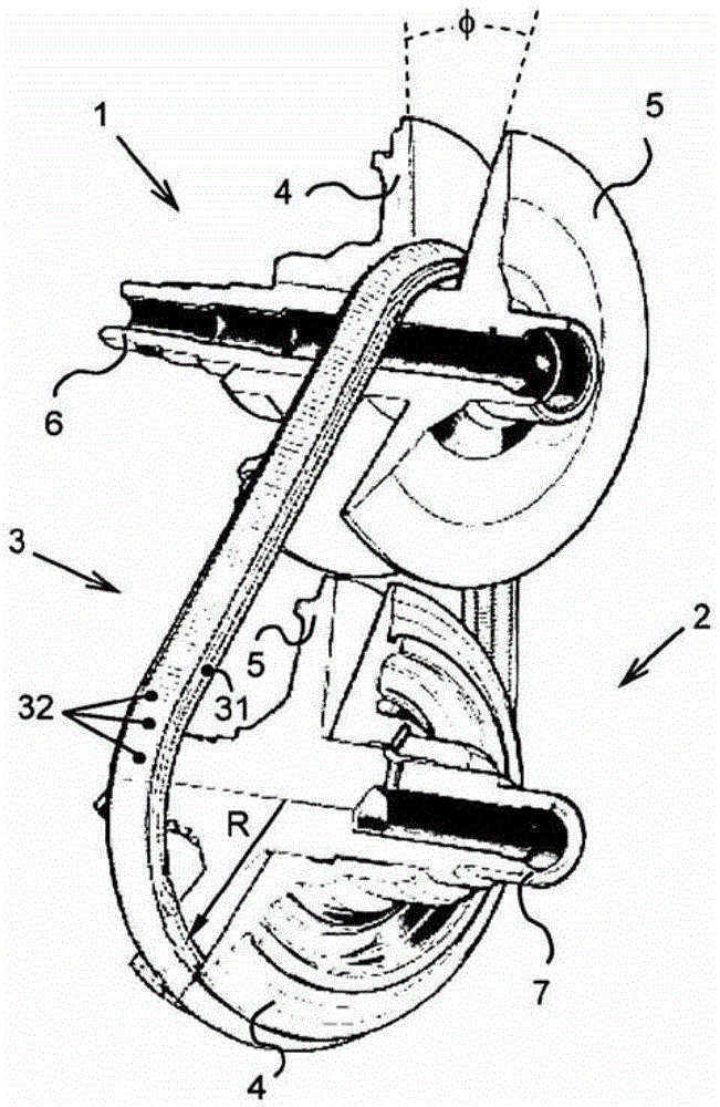
[0017] figure 1 A view of the main parts of a continuously variable transmission according to the prior art is schematically shown. Said known transmission comprises a first pulley 1 on a transmission input shaft 6 drivable by an engine (not shown) with a first (force) couple Tp, and a load (not shown) with a second couple Ts ) The second pulley 2 on the transmission output shaft 7. Both pulleys 1, 2 are provided with a substantially conical pulley disc 5 fixed invariably to the respective pulley shaft 6, 7 and provided with a shaft displaceable relative to said shaft 6, 7 in the axial direction. The same generally conical pulley wheel 4. The drive belt 3 is clamped between the pulley pulleys 4 , 5 of the two pulleys 1 , 2 , this drive belt in each case describes a path in the form of an approximately circular arc, ie a running radius R. Mechanical power can be transmitted between the two pulley shafts 6, 7 by means of the friction between the transmission belt 3 and the p...


PUM


Abstract

The invention relates to a drive belt for continuously variable transmission for motor vehicles, provided with two pulleys, each comprising two substantially conical pulley sheaves, between which the drive belt can be held at a variable radial position, which drive belt is provided with transverse elements (32), which on both lateral sides are provided with a flank (40) that is intended for frictional contact with the pulleys, in which flank (40) one or more grooves (41) of two different types are provided, whereof a first type of groove (50) is deeper than a second, more shallow type of groove (51).

Description

technical field [0001] The invention relates to a transmission belt, in particular for use in a continuously variable transmission with two variable pulleys with convex pulley pulleys. An example of a drive belt and associated transmission of the type described is described in International Patent Application Publication WO 2006 / 062400A1. This known drive belt is characterized, inter alia, by a series of transverse elements slidably mounted on a continuous, ie endless, tensioning element. Background technique [0002] When describing orientation with respect to a transverse element, it is always assumed that the transverse element is in a vertical position, e.g. figure 2 shown in its front view. In this figure, the longitudinal or circumferential direction of the drive belt is at right angles to the plane of the figure. exist figure 2 In all planes, the lateral or width direction is from left to right and the radial or height direction is from top to bottom. [0003] Kn...

Claims


Application Information

Patent Timeline
Patent Type & Authority Patents(China)
IPC IPC(8): F16G5/16
CPCF16G5/16F16H9/16
Inventor L·H·R·M·普林森
Owner ROBERT BOSCH GMBH
Why Eureka
Try Eureka