Method and device for binding optic disc base board, and liquid matter supply method

A technology for bonding devices and plate-shaped objects, which is applied to optical recording/reproduction, devices for coating liquid on the surface, optical discs, etc., which can solve the problems of small contact area and hollowness

Inactive Publication Date: 2008-11-26
ORIGIN ELECTRIC CO LTD
View PDF3 Cites 0 Cited by
  • Summary
  • Abstract
  • Description
  • Claims
  • Application Information

AI Technical Summary

Problems solved by technology

[0005] However, even with this method, it is extremely difficult to make the contact area of ​​the adhesive liquid film Ta and the adhesive liquid film Tb small enough at the moment of contact with each other, so it is impossible to make the micro hollow space completely void.
In addition, when the adhesive liquid film Ta or the adhesive liquid film Tb contacts the opposing optical disc substrate B or A, a hollow space may be generated.

Method used


Image

  • Method and device for binding optic disc base board, and liquid matter supply method
  • Method and device for binding optic disc base board, and liquid matter supply method
  • Method and device for binding optic disc base board, and liquid matter supply method

Examples


Embodiment 1

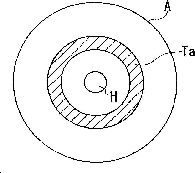
[0039] Figure 2 is used to illustrate Figure 1A A diagram of an example of forming an annular liquid film Ta of the adhesive shown. The adhesive supply nozzle 1 for supplying liquid adhesive to the optical disc substrate A is formed in a thin tube shape made of a common metal material, and performs a normal liquid supply operation. Adhesive supply nozzle 1 is connected to one terminal of AC power supply 2 and ground potential at the same time, and electrode mechanism 3 working as an electrode on the receiving table is connected to the other terminal of AC power supply 2 through switch 4 . Therefore, when the switch 4 is closed and the AC voltage from the AC power source 2 is applied between the adhesive supply nozzle 1 and the electrode mechanism 3, an AC electric field is formed therebetween. In the state where the AC electric field is formed, the receiving table is rotated at a constant speed for approximately one turn, and at the same time, a predetermined amount of liqui...


PUM


Abstract

The object of the present invention is to significantly inhibit the formation of voids between substrates bonded together when a liquid adhesive is supplied onto an optical disc substrate or when the optical disc substrate is bonded to another optical disc substrate. Accordingly, the present invention discloses a method for bonding two optical disc substrates together which comprises the steps of joining the optical disc substrates together with an adhesive and curing the adhesive, wherein the adhesive is supplied onto the optical disc substrate by an electric field formed between the adhesive-supplying nozzle, for supplying the adhesive onto the optical disc substrate and the two optical disc substrates are then joined together and subjected to spun by a spinning process.

Description

technical field [0001] The present invention relates to a bonding method and device for bonding optical disc substrates to produce one optical disc substrate, and a liquid supply method. technical background [0002] In the case of bonding optical disc substrates using an optical disc bonding apparatus using a liquid adhesive, it is important not to generate voids (bubbles) in the bonded adhesive layer. For this purpose, various methods have been considered in the past, but any method will form a cavity with a diameter of 0.1 mm or more, a micro cavity with a diameter of about 0.05 mm to 0.1 mm or less, or a mixture of these. [0003] The applicant of the present invention applied for the following invention in Japanese Patent Application No. Hei 10-257530, which is a method that can greatly improve these problems. refer to Figure 8 The invention of this application is described. Of the two optical disc substrates A and B, the adhesive surface of the lower optical disc su...

Claims


Application Information

Patent Timeline
Patent Type & Authority Patents(China)
IPC IPC(8): G11B7/26B05C5/02B29C65/04B29C65/52
CPCB29C66/452B29C66/21B29C65/7847B29C65/483B05C11/08B29L2017/005G11B7/26B29C65/521B05C5/02B05C9/12B29C65/04B05C5/0212B29C66/8322B29C66/8242B29C66/1122B29C66/723B29C65/7811B29C66/342G11B7/24047G11B2220/2537
Inventor 篠原信一小林秀雄中村昌宽加治宽也
Owner ORIGIN ELECTRIC CO LTD
Why Eureka
Try Eureka