
End piece for a retrofit fluorescent lamp and retrofit fluorescent lamp

A technology for fluorescent lamps and terminals, which is applied to the safety device of the lighting device, the cooling/heating device of the lighting device, the components of the lighting device, etc., which can solve the problems of high assembly cost and electric shock, and achieve the effect of simple implementation

Active Publication Date: 2012-09-12
LEDVANCE GMBH
View PDF5 Cites 4 Cited by
  • Summary
  • Abstract
  • Description
  • Claims
  • Application Information

AI Technical Summary

Problems solved by technology

[0003] Previous LED retrofit fluorescent lamps have the disadvantage that the screws can be unscrewed by means of simple mechanisms and the cover can then be easily removed
The driver electronics are therefore freely accessible such that there is a risk of electric shock
Furthermore, the assembly is relatively expensive due to the necessity of screwing and fitting the plastic cover

Method used


Image

  • End piece for a retrofit fluorescent lamp and retrofit fluorescent lamp
  • End piece for a retrofit fluorescent lamp and retrofit fluorescent lamp
  • End piece for a retrofit fluorescent lamp and retrofit fluorescent lamp

Examples


Embodiment Construction

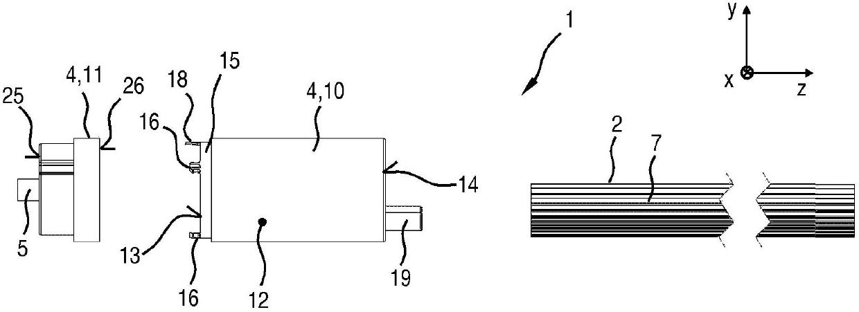
[0033] figure 1 shows a side view of part of an LED retrofit fluorescent lamp 1, and figure 2 A plan view of the LED retrofit fluorescent lamp 1 is shown. The LED retrofit fluorescent lamp 1 has a heat sink 2 as an intermediate part, which is covered on its two end sides 3a, 3b by end caps in each case. A terminal (not shown) provided for fastening at the end side 3a shown here on the right essentially serves to mechanically fasten the LED retrofit fluorescent lamp 1 in a conventional fluorescent lamp socket. Adjacent to the end side 3 b shown here on the left is a head 4 which is formed as a drive housing. In this case, the terminal 4 accommodates a driver (not shown), which converts the power supplied via the electrical connection 5 into a current or voltage suitable for the operation of the light-emitting diode 8 .

[0034] The end cap 4 has an at least approximately cylindrical outer contour, which is similar to that of a conventional fluorescent lamp. The cooling bod...


PUM


Abstract

The end piece (4) is provided for a retrofit fluorescent lamp (1), wherein the end piece (4) comprises a housing part (10) that is open on a first end face (13) and a cover (11) that can close the first end face (13), wherein the housing part (10) and the cover (11) can be non-releasably locked together. The retrofit fluorescent lamp (1) comprises such an end piece (4).

Description

technical field [0001] The invention relates to a terminal used for retrofit fluorescent lamps, in particular to LED retrofit fluorescent lamps. Background technique [0002] LED retrofit fluorescent lamps are supposed to replace traditional fluorescent lamps and use light-emitting diodes (LEDs) as light sources. LED retrofit fluorescent lamps can fit into lampholders designed for conventional fluorescent lamps, and should be close to conventional fluorescent lamps in shape and light emission characteristics. LED retrofit fluorescent lamps therefore also have a shape extending along the longitudinal axis which typically does not extend significantly beyond the cylindrical outer contour known from conventional fluorescent lamps. LED retrofit fluorescent lamps require drivers for driving light-emitting diodes. In some LED retrofit fluorescent lamps, the driver is placed in a terminal which then also functions as the driver housing. Until now, the terminal has a housing part...

Claims


Application Information

Patent Timeline
Patent Type & Authority Applications(China)
IPC IPC(8): F21K99/00F21V23/00F21V17/10F21V17/16F21Y101/02F21Y113/00
CPCF21V17/101F21V17/164F21V23/003F21V25/04F21V29/507F21V29/70F21K9/272F21K9/278F21Y2103/10F21Y2113/13F21Y2115/10F21V17/10F21V23/00F21V29/00
Inventor 哈拉尔德·代尔利安古念松刘晴斯特凡·奥岑
Owner LEDVANCE GMBH
Learn More