Oxidation regeneration device and method for caustic sludge containing NaSR
A regeneration device and a technology for alkali residues, which are applied in the preparation of alkali metal hydroxides, sulfides/polysulfides, and the removal of solid wastes, etc., can solve the problems of product liquefied gas, the increase of total sulfur in light gasoline, etc., and achieve the effect Good results
Active Publication Date: 2012-09-19
NINGBO ZHONGYI PETROCHEM TECH
View PDF8 Cites 2 Cited by
- Summary
- Abstract
- Description
- Claims
- Application Information
AI Technical Summary
Problems solved by technology
[0003] The lye used for desulfurization of liquefied gas and light gasoline is generally designed with oxidation regeneration facilities, but because most of them use traditional packed oxidation towers, the disulfides generated by oxidation cannot be separated, and with the accumulation of
Method used
View moreImage
Smart ImageViewing Examples
Examples
 PUM
 Abstract
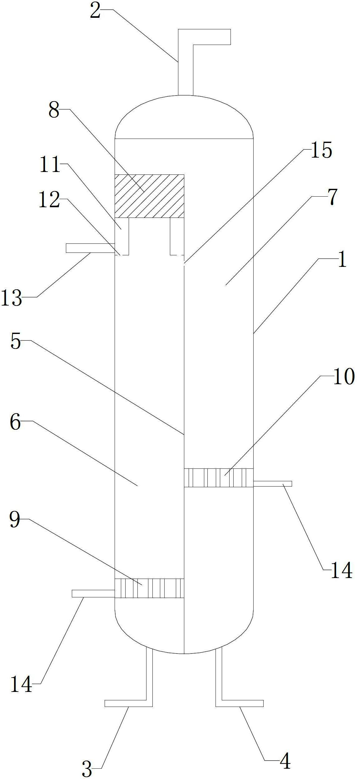
The invention relates to an oxidation regeneration device and method for caustic sludge containing NaSR. The oxidation regeneration device comprises a caustic sludge oxidation separating column. A partition is arranged inside the caustic sludge oxidation separating column, the inside of the caustic sludge oxidation separating column is divided into an oxidation area and a gas stripping and refined removing area by the partition, the bottom of the oxidation area is communicated with a caustic sludge feed pipe, the top and the bottom of the oxidation area are provided with a skimmer and a first gas distributor respectively, and the bottom of the gas stripping and refined removing area is communicated with a caustic sludge discharge pipe and is provided with a second gas distributor. The oxidation regeneration method includes: firstly, disulfide is discharged by oxidation of the caustic sludge by the aid of the oxidation area, secondly, residual disulfide is discharged with tail gas oxidized caustic sludge after entering the gas stripping and refined removing area, and thirdly, discharged gas is sent to burning equipment to be subjected to desulfurization. The oxidation regeneration device and method have the advantages that the full-phase contact microbubble technology is adopted, and accordingly the NaSR in the caustic sludge is oxidized to be reduced to below 1 ppm, and separation and recovery of disulfide are achieved.
Description
technical field [0001] The invention relates to an oxidation regeneration device and method for sodium mercaptide-containing alkali slag. Background technique [0002] Most of the liquefied petroleum gas produced by refineries adopts amine liquid extraction to remove hydrogen sulfide, and sodium hydroxide and sodium chloride aqueous solution to remove mercaptans. In recent years, with the increase in the total sulfur requirements of finished gasoline, more and more devices Gasoline is divided into light gasoline and heavy gasoline. Heavy gasoline is hydrodesulfurized, and light gasoline is washed with alkali to remove mercaptans, so as to reduce the cost of gasoline hydrodesulfurization. [0003] The lye used for desulfurization of liquefied gas and light gasoline is generally designed with oxidation regeneration facilities, but because most of them use traditional packed oxidation towers, the disulfides generated by oxidation cannot be separated, and with the accumulation o...
Claims
Login to View More Application Information
Patent Timeline
 IPC IPC(8): B09B3/00C01D1/04C01B17/20
Inventor 喻武钢聂通元王铭徐振华童仁可蔡喜洋贺立明施景杨仁宗
Owner NINGBO ZHONGYI PETROCHEM TECH
- R&D Engineer
- R&D Manager
- IP Professional
- Industry Leading Data Capabilities
- Powerful AI technology
- Patent DNA Extraction
Learn More Browse by: Latest US Patents, China's latest patents, Technical Efficacy Thesaurus, Application Domain, Technology Topic, Popular Technical Reports.
© 2024 PatSnap. All rights reserved.Legal|Privacy policy|Modern Slavery Act Transparency Statement|Sitemap|About US| Contact US: help@patsnap.com


