Rolling machine

A rolling mill and stand technology, applied in the direction of metal rolling, metal rolling, keeping roll equipment in an effective state, etc., can solve problems such as manual cleaning and affecting rolling efficiency, and achieve the effect of improving rolling efficiency

Inactive Publication Date: 2012-09-19
苏州中信科技股份有限公司
View PDF6 Cites 1 Cited by
  • Summary
  • Abstract
  • Description
  • Claims
  • Application Information

AI Technical Summary

Problems solved by technology

[0003]In the existing rolling mill, metal materials are rolled by rolls. After working for a long time, a lot of metal chips will be attached to the circumferential surface of the rolls. Manual cleaning, which affects rolling efficiency

Method used


Image

  • Rolling machine
  • Rolling machine
  • Rolling machine

Examples


Embodiment Construction

[0013] The present invention will be further described below in conjunction with the accompanying drawings.

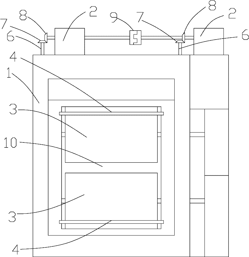
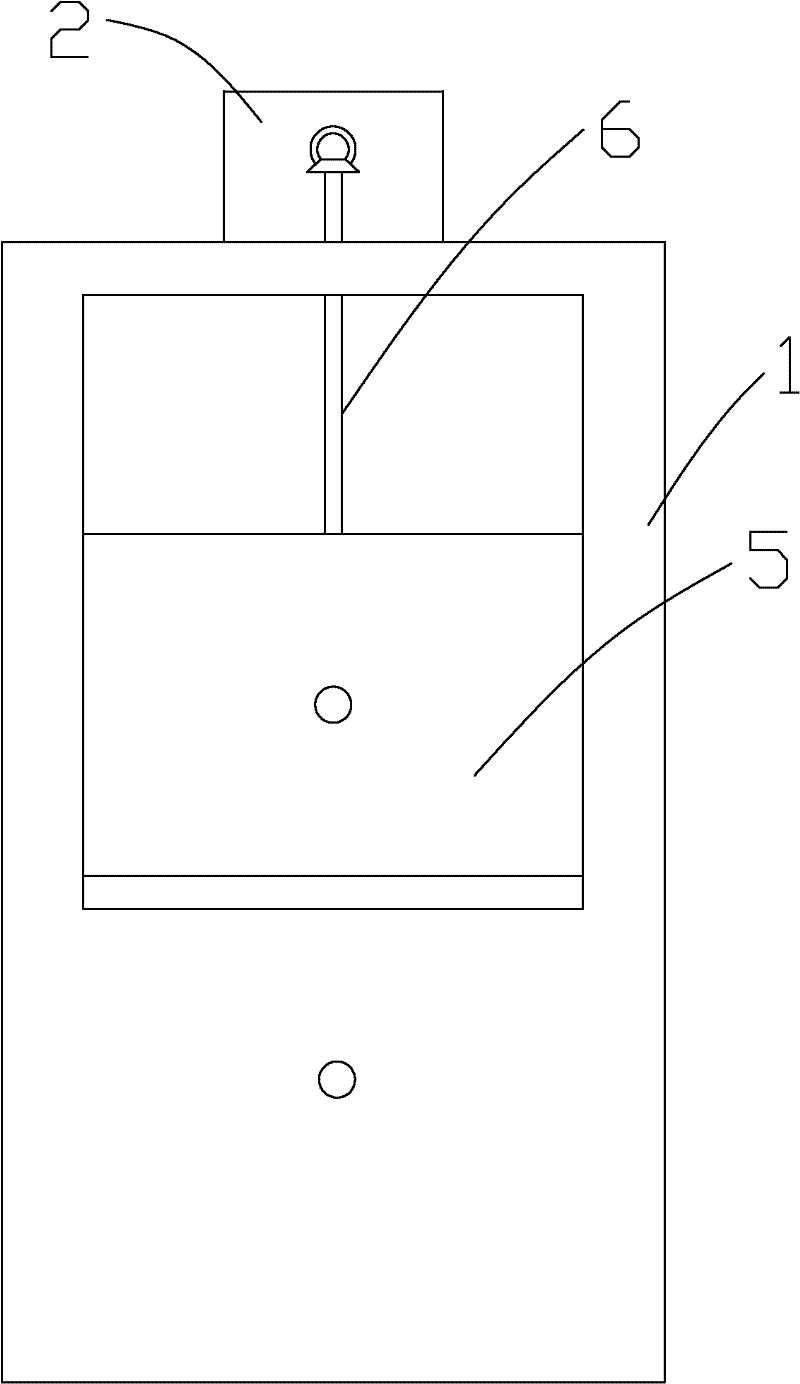
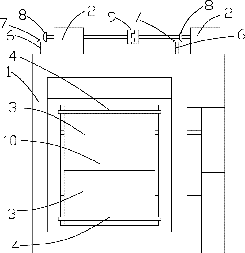
[0014] exist figure 1 and 2 Among them, a rolling mill, comprising a stand 1, a pair of rollers 3 arranged side by side on the stand 1 up and down and rotating in opposite directions, the axis lines of the rollers 3 are all arranged horizontally, and a rolling channel 10 is formed between the pair of rollers 3 , the metal material passes through the rolling passage 10, and is rolled into a suitable size by a pair of rollers 3 rotating in opposite directions. Blades 4 are respectively arranged above and below the rolling passage 10 on the stand 1, and the blade 4 of each blade 4 All extend along the axial direction of the roll 3 and are closely attached to the circumferential surface of the corresponding roll 3 . When the roll 3 rotates and rolls like this, the metal shavings attached on the roll 3 can be eradicated or removed by the blade of the blade 4 at the ...


PUM


Abstract

The invention discloses a rolling machine, comprising a machine base and a pair of rollers which are arranged on the machine base in parallel up and down and are rotated oppositely, wherein the axial leads of the rollers are arranged horizontally; a rolling channel is formed between a pair of the rollers; the machine base is provided with blades respectively above and below the rolling channel; the cutting edge of each blade is extended along an axial direction of a roller and is clung on the surface of the circumferential direction of a corresponding roller; and therefore, when the rollers are rotated in a rolling procedure, metal filing attached on the rollers are wiped or cleaned by cutting edges of the blades simultaneously so as to avoid trouble of manual cleaning; simultaneously, rolling efficiency is increased.

Description

[0001] technical field [0002] The invention relates to a rolling mill. Background technique [0003] In existing rolling mills, metal materials are rolled by rollers. After working for a long time, a lot of metal shavings will adhere to the circumferential surface of the rollers. At this time, manual cleaning is required, which affects the rolling efficiency. Contents of the invention [0004] The object of the present invention is to provide a rolling mill in which rolls are automatically cleaned by blade edges. [0005] In order to achieve the above object, the technical solution adopted by the present invention is: a rolling mill, comprising a stand, a pair of rolls arranged side by side on the stand up and down and rotating in opposite directions, the axis lines of the rolls are all arranged horizontally, A rolling channel is formed between the pair of rolls, blades are respectively arranged above and below the rolling channel on the stand, and the blades of each bl...

Claims


Application Information

Patent Timeline
Patent Type & Authority Applications(China)
IPC IPC(8): B21B1/00B21B28/02
Inventor 邱九根
Owner 苏州中信科技股份有限公司
Why Eureka
Try Eureka