A micro-climate intelligent adjustment system for courtyard public courtyards

A technology for regulating systems and microclimates, applied in snow traps, roof drainage, skylights/domes, etc., which can solve problems such as hidden safety hazards, inability to achieve ventilation from the ceiling, and low snow removal efficiency, and achieve the effect of preventing impacts.

Active Publication Date: 2021-04-06
HARBIN UNIV OF SCI & TECH
View PDF9 Cites 0 Cited by
  • Summary
  • Abstract
  • Description
  • Claims
  • Application Information

AI Technical Summary

Problems solved by technology

[0004] In order to solve the problem that the existing enclosed ceiling for courtyard public courtyards cannot realize ventilation, and relies on manual snow removal, the snow removal efficiency is low, time-consuming and labor-intensive, and has potential safety hazards, and further provides a public courtyard courtyard micro- Climate Intelligent Regulation System

Method used


Image

  • A micro-climate intelligent adjustment system for courtyard public courtyards
  • A micro-climate intelligent adjustment system for courtyard public courtyards
  • A micro-climate intelligent adjustment system for courtyard public courtyards

Examples


specific Embodiment approach 1

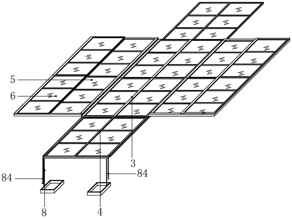
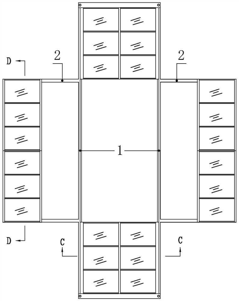
[0048] Specific implementation mode one: combine Figure 1 to Figure 3 Describe this embodiment mode, a kind of micro-climate intelligent adjustment system of courtyard public courtyard of this embodiment mode, it comprises two courtyard central ceilings, two courtyard edge ceilings, four courtyard central support structures 1 and four courtyard edge support structure 2;

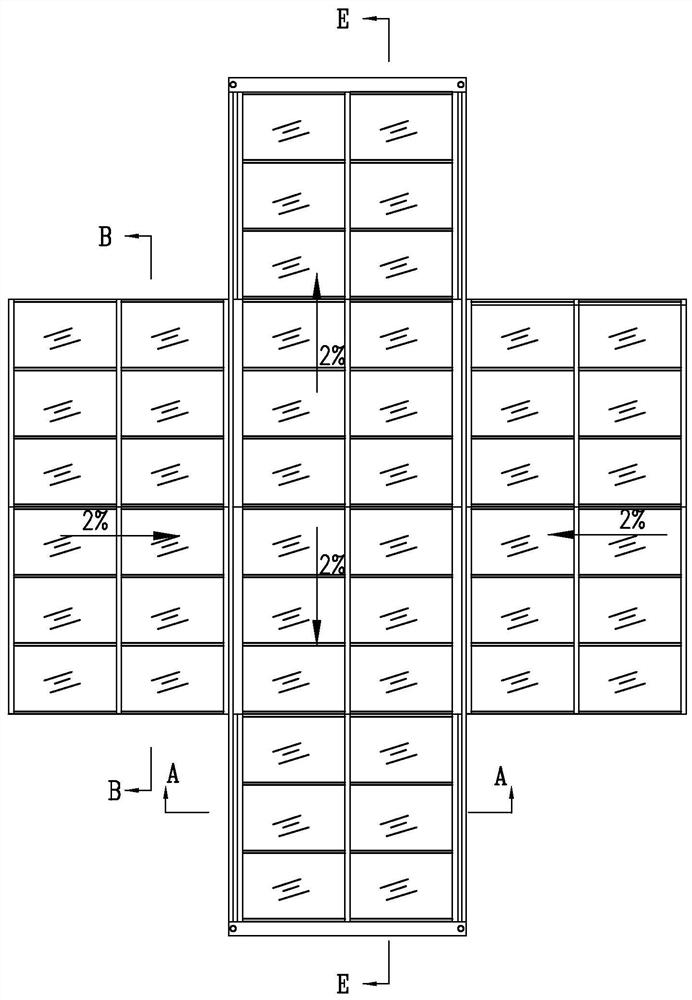
[0049] The ceilings in the middle of the two courtyards are arranged opposite to each other along the length direction of the public courtyard of the compound courtyard. The ceilings in the middle of the two courtyards are sealed and fit. Above, the support structure 1 in the middle of the courtyard is set with a slope from the middle to both ends, and the support structure 1 in the middle of the courtyard is set with a slope of 2%.

[0050] Each central courtyard ceiling includes a central courtyard movable module 3, a central courtyard fixed module 4, and a central courtyard sealing assembly 7, and the mo...

specific Embodiment approach 2

[0053] Specific implementation mode two: combination Figure 4 to Figure 7 Describe this embodiment, the compositions of the movable module 5 at the edge of the courtyard and the movable module 3 in the middle of the courtyard in this embodiment are the same;

[0054] The movable module 3 in the middle of the courtyard includes a movable lighting frame in the middle and two first movable electric ball screw slide rails 31 in the middle. Keel 33, multiple central movable lighting panels 34 and multiple central movable lighting panel supports 35, all of the central movable main joists 32 are arranged in parallel along the length direction of the courtyard central support structure 1, and the adjacent two central sections can be moved A plurality of middle movable sub-keels 33 are vertically evenly distributed between the main keels 32, and the middle movable main keels 32 and the middle movable sub-keels 33 are connected by bolts, and the middle movable main keels 32 and the mid...

specific Embodiment approach 3

[0064] Specific implementation mode three: combination Figure 4 and Figure 5 Describe this embodiment, the central movable snow removal device of the movable module 3 in the middle of the courtyard in this embodiment includes a movable snow scraper 36 in the middle, two movable electric ball screw slide rails 37 in the second middle and two first first in the middle. The protective cover 38 and the two second middle movable electric ball screw slide rails 37 are respectively fixed vertically on the upper surface of the middle movable main keel 32 located on both sides, and the middle movable snow scraper 36 is vertically arranged on the two second Between the movable electric ball screw slide rails 37 in the middle, the two ends of the movable snow scraper 36 in the middle are fixedly connected with the slide tables of the two second movable electric ball screw slide rails 37 in the middle respectively, and the movable snow scraper in the middle 36 includes a first steel pl...


PUM


Abstract

The invention relates to a micro-climate intelligent adjustment system of a courtyard public courtyard, which relates to the technical field of courtyard buildings. The invention solves the problem that ventilation cannot be realized in the existing enclosed ceiling for the public courtyard of a compound courtyard, and relying on manual snow removal has the problems of low snow removal efficiency, time-consuming and laborious work, and potential safety hazards. The ceilings in the middle of the two courtyards of the present invention are arranged opposite to each other along the length direction of the public courtyard of the courtyard. When the ceiling in the middle of the courtyard is in a ventilated state, the movable module in the middle of the courtyard slides outward to the upper part of the fixed module in the middle of the courtyard, and the ceilings in the two courtyards are arranged symmetrically. On both sides of the ceiling in the middle of the two courtyards, when the ceiling at the edge of the courtyard is in a ventilated state, the movable module at the edge of the courtyard slides outward to the lower part of the fixed module at the edge of the courtyard, the movable module in the middle of the courtyard, the fixed module in the middle of the courtyard, and the fixed module at the edge of the courtyard Both the movable module and the fixed module at the edge of the courtyard are equipped with snow removal devices. The invention is used to realize the intelligent regulation of the microclimate in the public courtyard of the courtyard.

Description

technical field [0001] The invention relates to the technical field of courtyard buildings, in particular to an intelligent adjustment system for the microclimate of public courtyards in courtyards. Background technique [0002] The traditional open public courtyard of Heyuan has severe weather such as high temperature in summer, cloudy rain, snow in winter, and low temperature, which will prevent the occupants from outdoor activities, entertainment, and rest, which greatly reduces the user's living experience. The canopy used to shelter from rain and snow in the existing Heyuan public courtyard is a closed structure, which cannot be ventilated. Moreover, the closed ceiling does not have the function of self-removing snow, and can only be removed by natural melting or relying on artificial snow removal, which has low snow removal efficiency, time-consuming and labor-intensive, and has potential safety hazards. [0003] To sum up, the existing enclosed ceilings for courtyard...

Claims


Application Information

Patent Timeline
Patent Type & Authority Patents(China)
IPC IPC(8): E04H1/12E04B7/16E04D13/10E04D13/035E04D13/04E04D13/064E04D13/076E04D13/08E04D13/03
CPCE04B7/166E04D13/033E04D13/0358E04D13/0404E04D13/064E04D13/0762E04D13/08E04D13/106E04D2013/034E04D2013/0873E04H1/1205
Inventor 王圣保王兴董可人张晨辉李鑫赵宇涵隋伊格张尉立苏娜
Owner HARBIN UNIV OF SCI & TECH
Why Eureka
Try Eureka