

Device for correcting automobile frame body
An automobile frame and body technology, which is applied in the field of automobile frame body correcting devices, can solve the problems of data deviation, unknown Z-axis deformation amount and deformation direction, difficult frame positioning and fixing, etc.
Inactive Publication Date: 2012-09-19
SHANGAHI SHOW KYOEL AUTOMOTIVE EQUIP
View PDF7 Cites 5 Cited by
- Summary
- Abstract
- Description
- Claims
- Application Information
AI Technical Summary
Problems solved by technology
Usual correcting machinery and tools (jacks, etc.) have the following disadvantages: 1. It is difficult to position and fix the frame
2. The deformation amount and deformation direction of the Z axis are unknown, and the workpiece needs to be turned over for reverse correction of deformation
3. Multiple clamping and fixing will cause deviations in the corrected data, resulting in repeated work
4. It is difficult to control the springback of the longitudinal beam after the correction force is released
5. Correction efficiency is low
Method used
View moreImage
Smart ImageViewing Examples

Examples
Embodiment Construction
Login to View More PUM
 Abstract
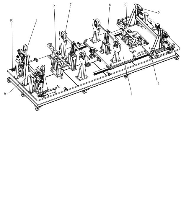
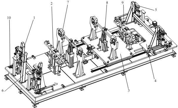
The invention discloses a device for correcting an automobile frame body, which comprises a front correction mechanism, a front jacking mechanism, a front slider, a rear slider, a rear correction mechanism, a guide column, a front clamping and positioning mechanism, a rear clamping and positioning mechanism, a rear jacking mechanism and a base plate, wherein the front correction mechanism and the guide column are arranged side by side, the front jacking mechanism is positioned behind the front correction mechanism, the front clamping and positioning mechanism is positioned behind the front jacking mechanism, the rear clamping and positioning mechanism is positioned on the front slider which is arranged behind the front clamping and positioning mechanism, the rear jacking mechanism is positioned behind the rear clamping and positioning mechanism, the rear correction mechanism is positioned on the rear slider which is arranged behind the rear jacking mechanism, and the front correction mechanism, the front jacking mechanism, the front slider, the rear slider, the rear correction mechanism, the guide column and the front clamping and positioning mechanism are all arranged on the base plate. The device can effectively correct buckling deformation ofthe head and tail parts of the automobile frame after welding.
Description
technical field [0001] The invention relates to a straightening device, in particular to a straightening device for an automobile frame body. [0002] Background technique [0002] Most of the welding of modern automobile frames adopts carbon dioxide shielded welding. Due to the different welding voltage, current, ambient temperature and personal operation methods, the deformation of individual frames will be out of tolerance. It is necessary to measure and correct the individual frames after welding. . Common rectifying machinery and tools (jack etc.) have following shortcoming: one, be difficult to vehicle frame is positioned and fixed. 2. The deformation amount and deformation direction of the Z axis are unknown, and the workpiece needs to be turned over for reverse correction of deformation. 3. Multiple clamping and fixing will cause deviations in the corrected data, resulting in repeated work. 4. It is difficult to control the springback of the longitudinal beam a...
Claims
Login to View More Application Information
Patent Timeline
 IPC IPC(8): B21D1/12
Inventor田永鑫杨斌李育赐刘彪王正锋
OwnerSHANGAHI SHOW KYOEL AUTOMOTIVE EQUIP