Supercharge Your Innovation With Domain-Expert AI Agents!

Manufacturing device of reinforcing steel bar cage of centrifugal force concrete pipe pile

A concrete pipe pile and manufacturing device technology, which is applied in the direction of manufacturing tools, resistance welding equipment, welding equipment, etc., can solve problems such as low production efficiency and shaft tendon bending, and achieve the goal of improving work efficiency, improving production efficiency, and saving installation time Effect

Active Publication Date: 2012-09-19
宁波中淳高科股份有限公司
View PDF5 Cites 9 Cited by
  • Summary
  • Abstract
  • Description
  • Claims
  • Application Information

AI Technical Summary

Problems solved by technology

[0003] The manufacturing device of the steel cage based on this chuck pulling manufacturing method has the following problems in the actual operation process: workers need to manually install the left end plate 203 and the right end plate 205 to the two ends of the steel cage main body 004, because the steel cage main body 004 Generally, they are relatively long, and the weight of the steel bars on the steel cage is relatively high. In this case, after a circle of steel bars are welded on the periphery of the shaft bar, the big head 304 of the shaft bar is affected by the gravity of the steel bars welded on it. The impact will tilt up, and at the same time, when welding the peripheral steel bars of the axle bar, the axle bar will also be bent. The above two reasons often cause the head 304 of the axle bar and the axle bar socket 207 on the end plate to be incompatible. Alignment, so when installing the end plate, workers need to straighten the big heads 304 of the shaft bars that have deviated from the position one by one. However, the number of shaft bars in a steel cage varies from ten to dozens, and 20 shaft bars For example, when installing the end plate, workers must first straighten the shaft bars at one end of the steel cage to the positions corresponding to the holes on the end plate, so that the end plate at this end can be installed in place, and then repeat the reinforcement. Install the end plate at the other end after the shaft rib at the other end of the cage is straightened in place
If there are 20 axle ribs, workers may need 40 straightening operations. Obviously, the production efficiency of this manufacturing method is very low.

Method used


Image

  • Manufacturing device of reinforcing steel bar cage of centrifugal force concrete pipe pile
  • Manufacturing device of reinforcing steel bar cage of centrifugal force concrete pipe pile
  • Manufacturing device of reinforcing steel bar cage of centrifugal force concrete pipe pile

Examples


Embodiment Construction

[0028] The present invention will be further described in detail below in conjunction with the drawings.

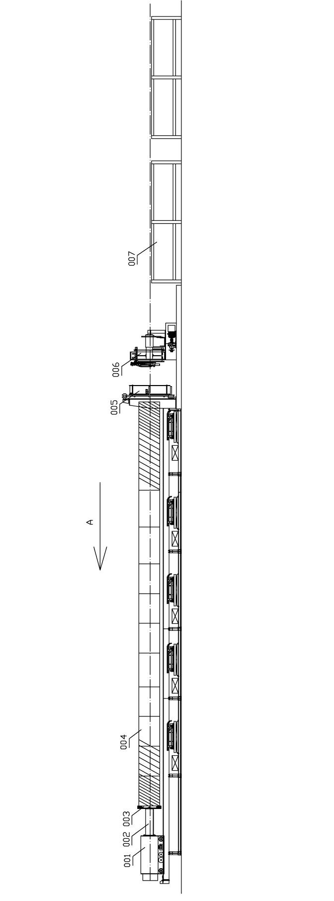
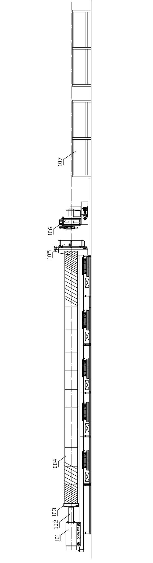
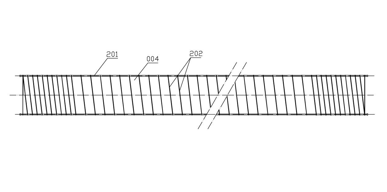
[0029] Attached figure 2 And Figure 7 , A manufacturing device for the reinforcement cage of centrifugal concrete pipe piles, which includes a traction device for pulling the shaft reinforcement 201 of the reinforcement cage and a welding machine for welding the spiral reinforcement 202 to the periphery of the shaft reinforcement of the reinforcement cage. The traction device is installed In front of the welding machine, an end plate clamping platform 103 for installing the end plate of the steel cage is provided on the traction device.

[0030] Further binding Figure 8 To attach Picture 11 , The traction device is a traction trolley 101, the welding machine is a seam welding machine 106, the traction trolley 101 is provided with a traction arm 102, and the end of the traction arm 102 is installed with an end plate clamping platform 103, the The end plate chuck 103 includ...


PUM


Abstract

The invention relates to a manufacturing device of a reinforcing steel bar cage of a centrifugal force concrete pipe pile. The manufacturing device comprises a drawing device for drawing shaft ribs (201) of the reinforcing steel bar cage, and a welding machine for welding spiral ribs (202) on the periphery of the shaft ribs of the reinforcing steel bar cage. The drawing device is mounted in front of the welding machine. The manufacturing device is characterized in that an end board clamping table (103) for mounting an end board of the reinforcing steel bar cage is arranged on the drawing device. The invention provides the manufacturing device of the reinforcing steel bar cage of the centrifugal force concrete pipe pile, which has higher production efficiency.

Description

Technical field [0001] The invention relates to a manufacturing device for a steel cage of centrifugal concrete pipe piles. Background technique [0002] In modern technology, centrifugal concrete pipe piles are widely used in various civil engineering, and the indispensable support body in centrifugal concrete pipe piles is the steel cage. In the prior art, the manufacturing device of the reinforced cage of the centrifugal concrete pipe pile adopts the chuck traction manufacturing method. This method uses the chuck to block the shaft reinforcement of the reinforced cage one by one, and then pulls the chuck by the traction trolley When the shaft reinforcement passes through the seam welding machine, the seam welding machine welds the steel bars to the shaft reinforcement in a spiral line along the outer ring of the shaft reinforcement when the shaft reinforcement passes, thereby forming a very long straight tube. After the steel cage body is completely welded, the steel cage bod...

Claims


Application Information

Patent Timeline
Patent Type & Authority Applications(China)
IPC IPC(8): B23K11/00B23K11/36
Inventor 长谷山国广张日红
Owner 宁波中淳高科股份有限公司
Features
  • R&D
  • Intellectual Property
  • Life Sciences
  • Materials
  • Tech Scout
  • Unparalleled Data Quality
  • Higher Quality Content
  • 60% Fewer Hallucinations
Learn More