Welding apparatus for induction motor

A technology for induction motors and welding equipment, applied in welding equipment, arc welding equipment, manufacturing motor generators, etc., can solve the problems of time-consuming, expensive, etc., and achieve reduced work cycle time, good heat transfer capacity, and high conductivity. effect of influence

Inactive Publication Date: 2015-06-17
GM GLOBAL TECH OPERATIONS LLC
View PDF6 Cites 0 Cited by
  • Summary
  • Abstract
  • Description
  • Claims
  • Application Information

AI Technical Summary

Problems solved by technology

[0003] Known methods of manufacturing induction motor rotors are time consuming and relatively expensive

Method used


Image

  • Welding apparatus for induction motor
  • Welding apparatus for induction motor
  • Welding apparatus for induction motor

Examples


Embodiment Construction

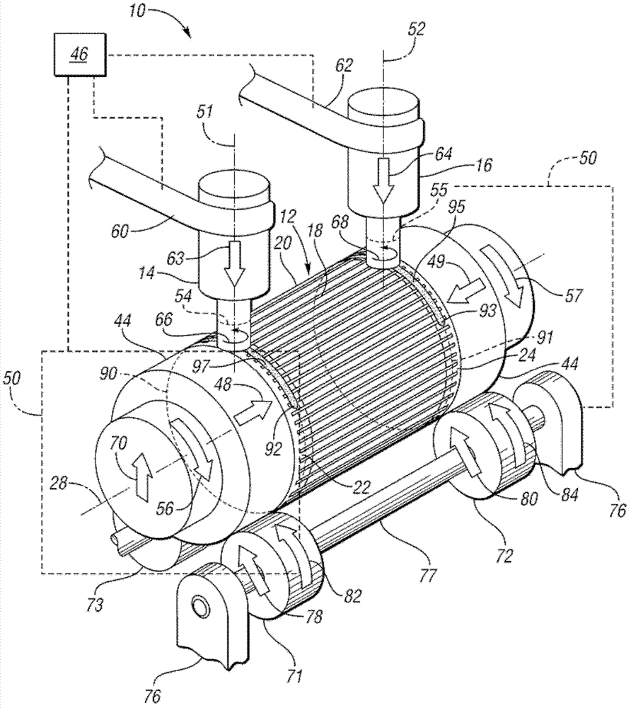
[0021] Referring to the drawings, wherein like reference numerals represent like parts throughout the several views, figure 1 A first embodiment of a welding apparatus 10 for welding an alternating current (AC) induction motor 12 is shown. Specifically, welding apparatus 10 uses first and second friction stir welding (FSW) heads 14, 16 to weld conductor bars 18 of annular rotor 20 of induction motor 12 to first and second shorting rings 22, 24, respectively. The short-circuit rings 22, 24 are preferably copper alloys or aluminum alloys. As described further below, the welding heads 14, 16 simultaneously weld the conductor bar 18 to the shorting rings 22, 24 with the welding heads 14, 16 held relatively stationary and the rotor 20 rotated to weld along a dual circular welding path. .

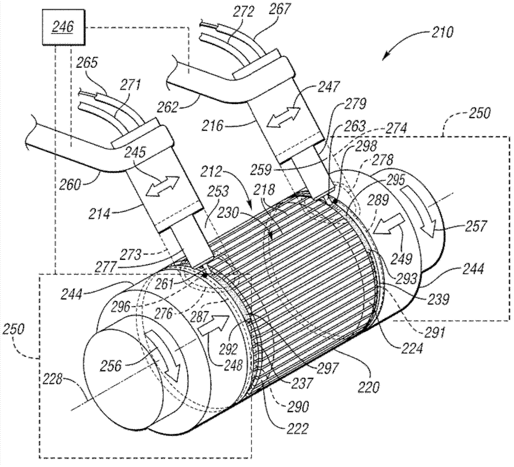
[0022] see Figure 7 , shows the rotor 20 before the conductor bars 18 are welded to the shorting rings 22 , 24 . When complete, induction motor 12 will also include a stator, not shown. The...


PUM


Abstract

A welding apparatus for an induction motor includes a fixture operable to support a rotor and rotate the rotor about an axis of rotation of the motor, and a welding head supported adjacent the fixture and operable to weld conductor bars located about the surface of the rotor to the first shorting ring when the fixture supports the rotor. A controller controls the fixture to selectively rotate the rotor. The controller moves the welding head, the fixture, or both, so that the welding head is in a welding position, and causes the welding head to weld the conductor bars to the first shorting ring while remaining in the welding position, with the rotor rotating to create a substantially circular weld path along the first shorting ring. In some embodiments, the conductor bars are welded to both shorting rings simultaneously. A method of welding an induction motor is also provided.

Description

technical field [0001] The invention relates to a welding device and a welding method for welding conductor bars to short-circuit rings of an induction motor. Background technique [0002] An alternating current (AC) induction motor is a specific type of electric motor that uses an induced current to magnetize portions of the motor's rotor during operation of the motor. The induced current flows through conductor bars parallel to the axis of rotation of the rotor and around the circumference of the rotor core. [0003] Known methods of manufacturing induction motor rotors are time consuming and relatively expensive. A common practice is to assemble prefabricated conductor bars and shorting rings onto a laminate stack and braze the components together. Another known method is to die cast the shorting rings and conductor bars together in a mold around the rotor stack. With some materials, such as copper, die casting is difficult to perform while maintaining the integrity of...

Claims


Application Information

Patent Timeline
Patent Type & Authority Patents(China)
IPC IPC(8): B23K31/02H02K15/00
CPCH02K15/0012B23K9/028B23K2101/38
Inventor B.E.卡尔森R.M.克雷伯R.T.齐曼斯基J.S.阿加皮奥D.R.西格勒
Owner GM GLOBAL TECH OPERATIONS LLC
Why Eureka
Try Eureka