
Status display apparatus

Inactive Publication Date: 2011-11-10
MITSUBISHI ELECTRIC CORP
View PDF7 Cites 0 Cited by
  • Summary
  • Abstract
  • Description
  • Claims
  • Application Information

AI Technical Summary

Benefits of technology

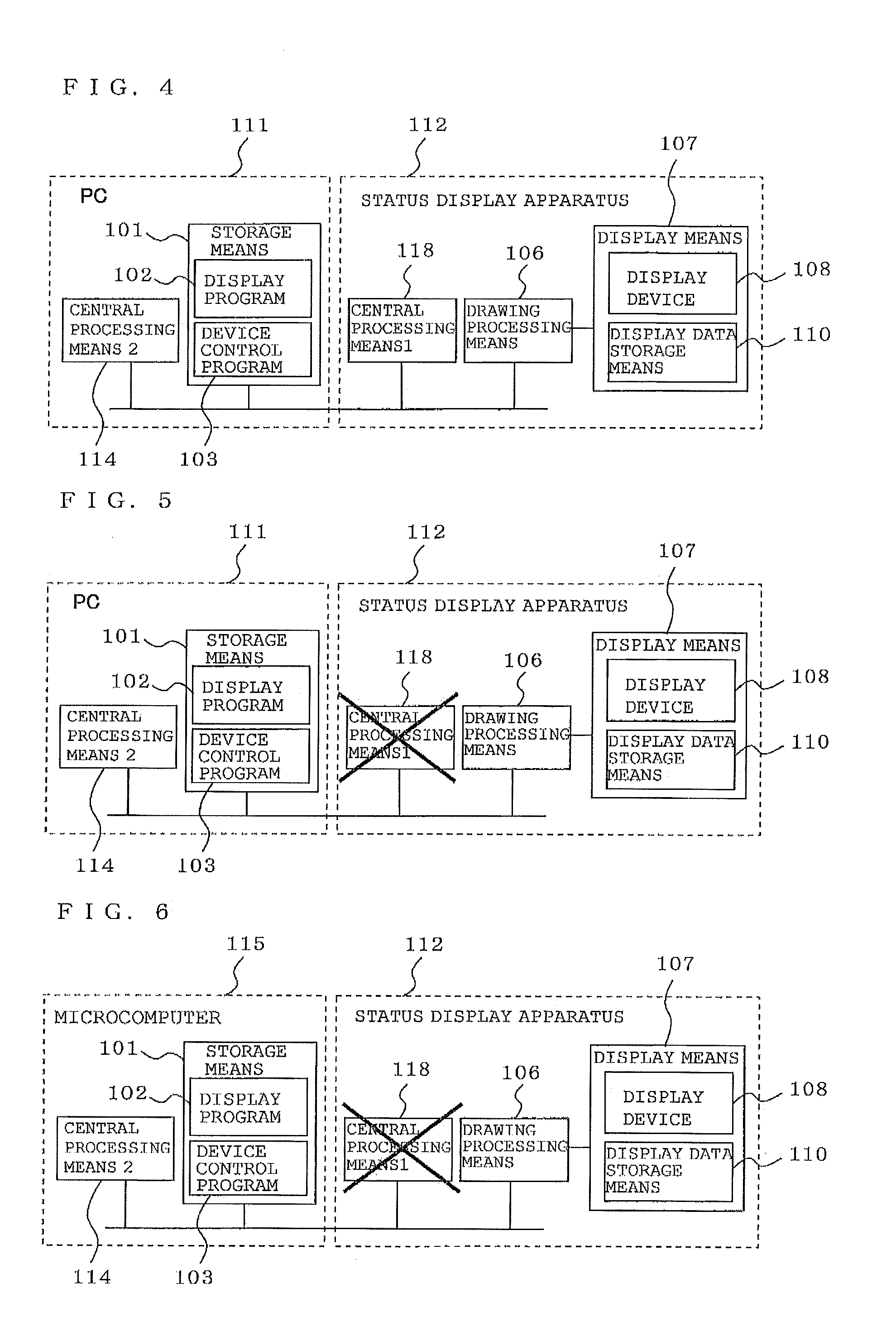
[0011]According to the status display apparatus of the present invention, a status display apparatus which enables display on an actual device as a result of drawing processing being performed in an actual built-in device can be realized under the control of a development environment such as a personal computer. Hence, a development environment is obtained which makes it easy to verify the performance, processing load, and display status in the actual built-in device, and realizes a decreased work cycle time during development and high work efficiency.

Problems solved by technology

Due to the increased functionality of electronic devices, such as air conditioners or electronic home appliances, it has become difficult to operate such devices by using only a fixed-content display apparatus, which is directly connected to several buttons, such as a combination of segmented liquid crystal displays.
However, in the display apparatus used in these devices, there are considerable restrictions on content displayed by a liquid crystal device and on an operation apparatus from the viewpoint of manufacturing cost.
From the viewpoints of cost, heat generation, and power consumption, a microcomputer used in a built-in device has low processing performance compared with a personal computer, and has a relative performance of less than 1 / 100 in speed and 1 / 1000 in memory capacity in many cases.
For GUI processing in which such graphic objects are combined and, further, drawing is frequently performed due to switching of display screens, most of the processing power of the microcomputer is consumed, and in addition, most of the memory capacity is consumed for intermediate information processing.
This causes execution of primary application programs for controlling air conditioners or home appliances to be delayed, for example.
Consequently, it becomes difficult to design control application programs, and in many situations complex combinations of GUI processing and control application processing are required to maintain satisfactory overall performance.
Accordingly, when some failure occurs, it becomes very difficult to determine whether this is a drawing request error, a control application processing error, or another processing error so as to isolate the cause.
It is difficult to develop a system which works properly, while isolating the causes of such failures and solving the problems, directly on a microcomputer having the severe restrictions described above.
When a screen is displayed using emulation or simulation in this manner, since display is performed on a display apparatus having characteristics different from those in the actual built-in device, there is a problem in that it is impossible to verify visibilities, differences in display among liquid crystal panels having different numbers of displayable colors, and the like.

Method used


Image

  • Status display apparatus
  • Status display apparatus
  • Status display apparatus

Examples


embodiment 1

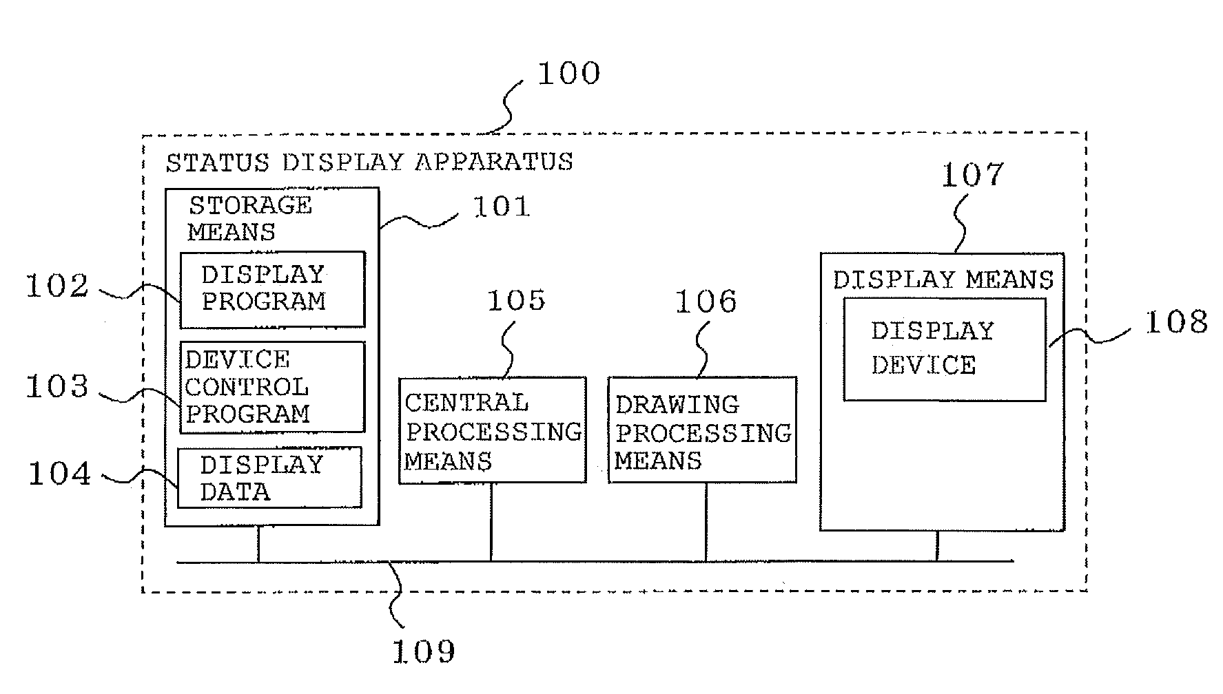
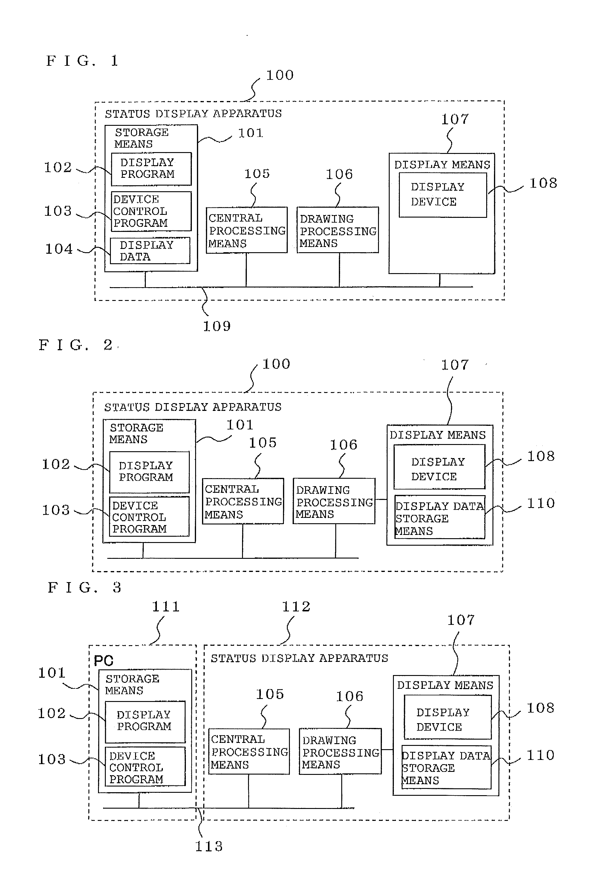
[0024]FIGS. 1, 2, 3, 4, 5, 6, 7, and 8 illustrate exemplary schematic configurations of a status display apparatus according to Embodiment 1 of the present invention.

[0025]Referring to FIGS. 1, 2, 8, and 9, the configurations and basic operations of the status display apparatus are described.

[0026]A status display apparatus 100 includes central processing means 105, drawing processing means 106, display means 107, and storage means 101, and the storage means 101 contains a display program 102, a device control program 103, and display data 104.

[0027]The operations are described with reference to FIGS. 1, 8, and 9 assuming that a display device 108 of the display means 107 is a full-dot liquid crystal display device.

[0028]The display means 107 displays, through illumination at high speed, content in accordance with shifting of a display position from the top left to the right and then downward on the full-dot display device sequentially with time, thereby displaying a two-dimensional...


PUM


Abstract

Provided is a development environment which makes it easy to verify the performance, processing load, and display status in an actual built-in device, enabling a reduced work cycle time during development and high work efficiency. Display means, central processing means, drawing processing means, and storage means are provided. The central processing means, at every predetermined operation unit clock, interprets content stored in the storage means at an instruction address and performs various computation processing. The drawing processing means shares the storage means with the central processing means and performs drawing processing. The display means shares with the drawing means a predetermined memory space starting at a display address in the storage means and makes a display device perform display in accordance with the memory state of the predetermined memory space starting at the display address. The storage means and / or central processing means is allowed to be provided outside of the status display apparatus.

Description

TECHNICAL FIELD[0001]The present invention relates to a status display apparatus and a method for displaying the status of a device such as an air conditioner or an electronic device.BACKGROUND ART[0002]Due to the increased functionality of electronic devices, such as air conditioners or electronic home appliances, it has become difficult to operate such devices by using only a fixed-content display apparatus, which is directly connected to several buttons, such as a combination of segmented liquid crystal displays. Hence, devices have come to be recently produced, which realize both multi-functionality and ease of use by displaying any graphics / images using a general purpose liquid crystal (a so-called full-dot liquid crystal) device which is getting to be a reasonable price or the like, and further through the use of this capability, by using a method (a so-called graphical user interface: GUI) of switching display screens, often in combination with displaying explanation windows ...

Claims


Application Information

Patent Timeline
IPC IPC(8): G06F13/14
CPCG06F3/1415G09G3/006G06F11/324
Inventor KOMIYA, NORIYUKIKUSHIRO, NORIYUKINAKATA, MASANORIKATSUKURA, MAKOTO
Owner MITSUBISHI ELECTRIC CORP
Learn More