Rubber rod clamp
A glue rod and beading technology, which is applied in printing, binding, etc., can solve the problems of piercing documents, scratching human hands, and high production costs, and achieves the effects of meeting environmental protection requirements, convenient disassembly and assembly, and cost saving
- Summary
- Abstract
- Description
- Claims
- Application Information
AI Technical Summary
Problems solved by technology
Method used
Image
Examples
Embodiment 1
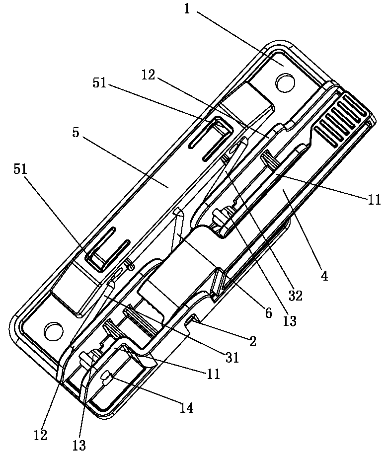
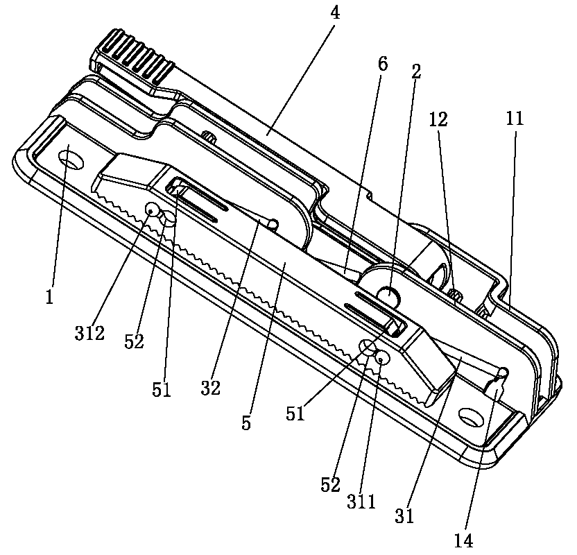
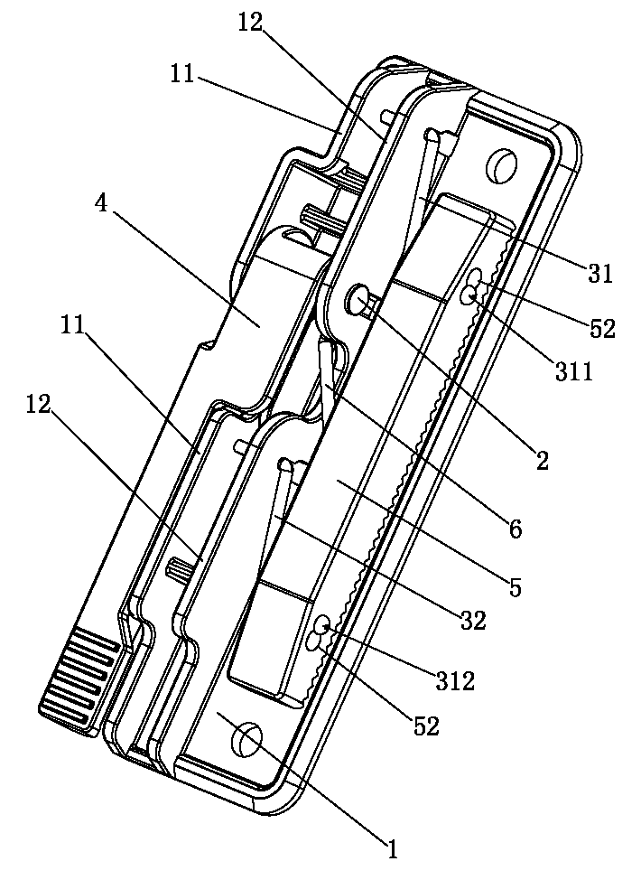
[0041] Such as Figure 1 to Figure 3 As shown, a glue rod clamp includes a front pivoting arm 31, a rear pivoting arm 32 and a pin 2, and a bottom plate 1, a handle 4 and a pressure strip 5 made of plastic. The handle 4 is pivotally connected to the side of the bottom plate 1 through the pin 2 On the side 11, a torsion spring 6 is sleeved on the pin 2. The first end and the second end of the torsion spring 6 are respectively connected to the pressing bar 5 and the handle 4; the front pivoting arm 31 and the rear pivoting arm 32 are in a "Z" shape, The arm 31 and the rear pivoting arm 32 are respectively arranged on both sides of the torsion spring 6. The first end and the second end of the front pivoting arm 31 are respectively movably connected to the pressure bar 5 and the bottom plate 1; the end of the first end of the front pivoting arm 31 extends To the outer surface of the bead 5, and the first end of the front swivel arm 31 is detachably connected to the bead 5, the end o...
Embodiment 2
[0054] Such as Figure 4 to Figure 8 As shown, the difference between this embodiment and the first embodiment is:
[0055] Wherein, the side surface of the inner end and the outer end of the bead 5 are respectively provided with a first T-shaped groove 52 for installing the first end of the front arm 31, and a first T-shaped groove 52 on the inner end of the bead 5 and the outer end of the bead 5 A shaft hole 7 is formed alternately at one end with a smaller width; the first end of the front pivoting arm 31 penetrates through the pivoting hole 7 formed by the first T-slots 52 at the inner and outer ends of the bead 5, the front pivoting arm 31 The first end of the front boom is formed with a first abutment 311 for the front boom, and the first abutment 311 abuts against the side surface of the outer end of the bead 5. When assembling, the first front abutment 311 of the first end of the front boom 31 passes through the first T-slot 52 at the inner end of the bead 5, and then pa...
Embodiment 3
[0058] Such as Picture 9 As shown, the difference between this embodiment and the first embodiment or the second embodiment is:
[0059] Wherein, the side surface of the inner end of the bead 5 is provided with a perforation 53 through which the first end of the front arm 31 passes, and the side of the outer end of the bead 5 is provided with a notch 54 for the first end of the front arm 31 to pass through, and The notch 54 penetrates the side surface of the outer end of the bead 5 and the top surface of the bead 5, the first end of the front swing arm 31 passes through the perforation 53 at the inner end of the bead 5 and the gap 54 at the outer end of the bead 5, and the first end of the front swing arm 31 A first bending hook 312 of the front turning arm is formed at the end, and the first bending hook 312 of the front turning arm abuts against the side surface of the outer end of the bead 5. When assembling, the first end of the front arm 31 passes through the perforation 53...
PUM
 Abstract
Description
Claims
Application Information
 - R&D
- Intellectual Property
- Life Sciences
- Materials
- Tech Scout
- Unparalleled Data Quality
- Higher Quality Content
- 60% Fewer Hallucinations
Browse by: Latest US Patents, China's latest patents, Technical Efficacy Thesaurus, Application Domain, Technology Topic, Popular Technical Reports.
© 2025 PatSnap. All rights reserved.Legal|Privacy policy|Modern Slavery Act Transparency Statement|Sitemap|About US| Contact US: help@patsnap.com


