Wire coiling and uncoiling device

A wire coil and wire technology, which is applied in the direction of using the reel take-up reel/photosensitive drum arrangement, etc., can solve the problems of single positioning and use interference, and achieve the effects of reducing friction, eliminating sound interference and accurate positioning.

Active Publication Date: 2012-09-19
DONGGUAN DADIAN ELECTRONICS +2
View PDF12 Cites 19 Cited by
  • Summary
  • Abstract
  • Description
  • Claims
  • Application Information

AI Technical Summary

Problems solved by technology

However, the arc track of the rotating body of the wire coiling device in the prior art has high and low steps, so when the ball moves between the arc tracks, it will make a certain sound and cause interference in use; moreover, the rotation of the wire coiling device The arc track of the body usually only has the function of single positioning

Method used


Image

  • Wire coiling and uncoiling device
  • Wire coiling and uncoiling device
  • Wire coiling and uncoiling device

Examples


Embodiment 1

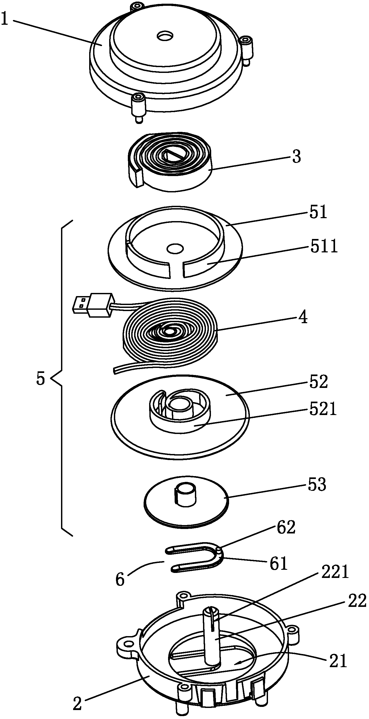
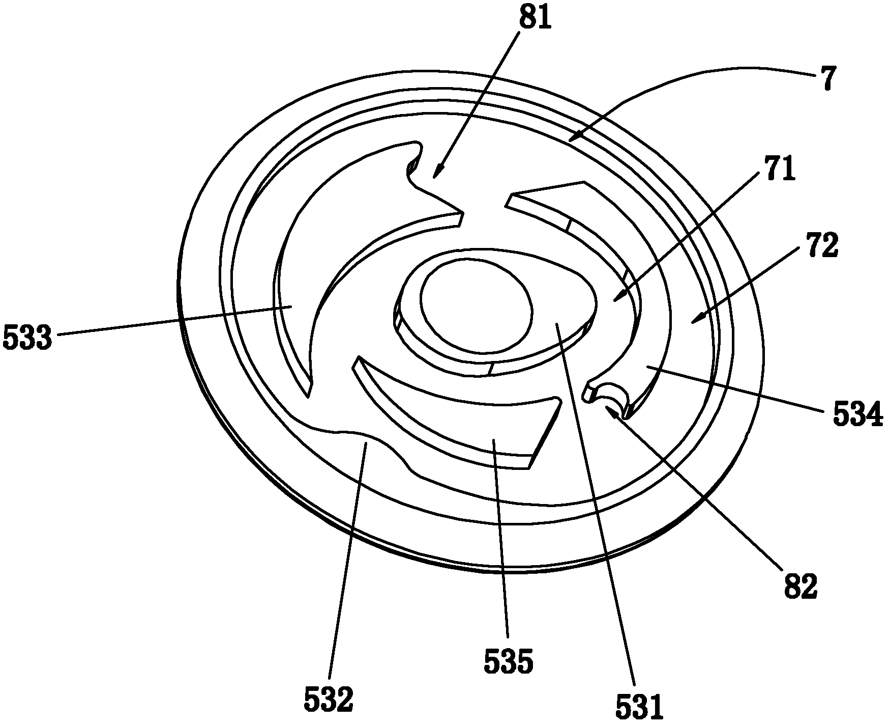
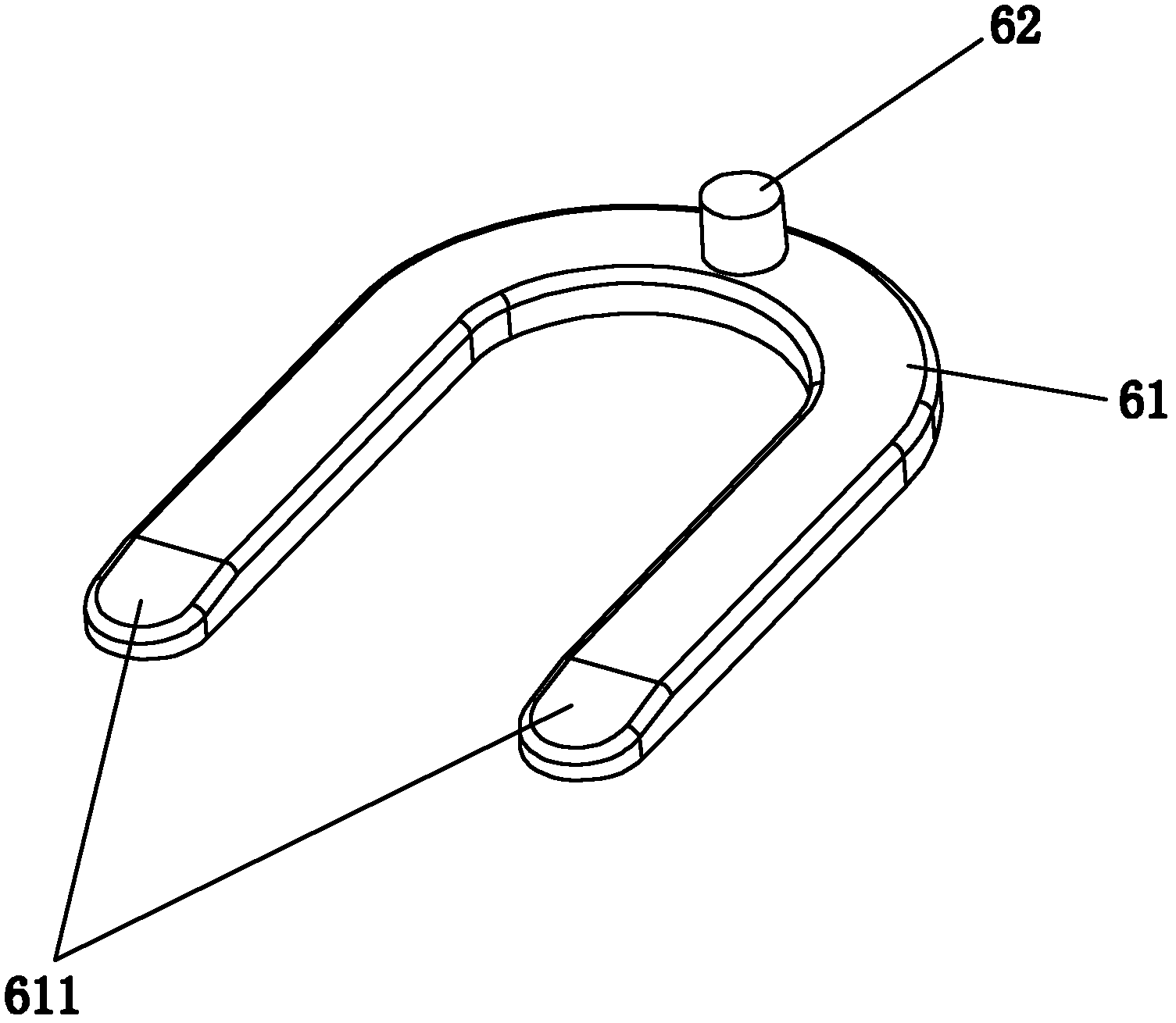
[0032] A kind of wire coiling device of the present invention, such as Figure 1~3 As shown, it includes an upper casing 1, a lower casing 2, a scroll spring 3, a wire 4, a rotating assembly 5 for winding the wire 4 and pressing the scroll spring 3, the upper casing 1 and the lower casing 2 interlocking, the scroll spring 3 is fixed between the upper casing 1 and the lower casing 2, the rotating assembly 5 is rotatably installed between the upper casing 1 and the lower casing 2, the rotating assembly 5 and the lower casing 2 is provided with a movable tenon 6 for positioning, the inner side of the lower shell 2 is provided with a limit groove 21 matching the movable tenon 6, and the bottom of the rotating assembly 5 is provided with a plane track for the movable tenon 6 to move 7. The plane track 7 includes an inner track 71 and an outer track 72. Between the inner track 71 and the outer track 72, there are a first positioning point 81 and a second positioning point that can b...

Embodiment 2

[0044] Embodiment 2 of a wire unwinding device of the present invention is different from Embodiment 1 in that the wire unwinding device is also provided with a safety catch 9 for manually locking the rotating assembly 5 . After the user pulls out the wire 4 for a certain length, the scroll spring 3 is already in a state with a relatively large rolling elastic force. The unwinding device is in the automatic winding state, and the rolling elastic force of the scroll spring 3 is released in an instant, which is very likely to cause the whole device to pop up suddenly and hurt the user, for example: the device placed in the trouser pocket pops up suddenly and hurts and the user's face. The present invention can manually lock the rotating assembly 5 through the safety catch 9, and only when the user manually releases the safety catch 9, can the wire winding device be in the automatic winding state, thereby preventing the above-mentioned situation from happening.

[0045] Specific...

Embodiment 3

[0050] Embodiment 3 of a wire coiling and unwinding device of the present invention, the difference between this embodiment and Embodiment 1 is that please refer to Figure 12 , both ends of the wire 4 are connected with an external stretching interface (such as: USB interface, earphone plug, etc.) outside the housing, thereby forming a double-stretching wire winding device, wherein, Figure 12 It is an exploded diagram of a double-stretched wire coiling device upside down. More specifically, its rotating assembly 5 is a rotating disk, and the plane track 7 is set at the bottom of the rotating disk, and the scroll spring 3 is placed on the top of the rotating disk. In the cavity, the wire 4 is wound around the periphery of the rotating disk, and the shaft 22 and the embedding groove 221 are arranged inside the upper casing 1 . Of course, the single-stretch, double-stretch or multi-stretch wire winding and unwinding devices made by adopting the principle and structure of the pr...


PUM


Abstract

The invention relates to the technical field of coiling and uncoiling devices, in particular to a wire coiling and uncoiling device which comprises an upper casing, a lower casing, a spiral spring, wires and a rotation component. The upper casing and the lower casing are mutually fastened, and a movable tenon is arranged between the rotation component and the lower casing. The inner side of the lower casing is provided with a limit groove, the bottom of the rotation component is provided with a planar rail, and the movable tenon can move on the planar rail. By means of the planar rail, no high and low steps are arranged between an inner ring and an outer ring of the planar rail so that the movable tenon makes low noise when moving in the planar rail, and accordingly sound interference can be eliminated and friction force can be reduced. A first positioning position and a second positioning position for positioning the movable tenon are arranged between the inner ring and the outer ring of the planar rail, and thereby dual-positioning function is realized, the wires can be more accurately positioned when being coiled or uncoiled, and deviations of the rotation component after long-time positioning can be balanced and scattered.

Description

technical field [0001] The invention relates to the technical field of winding and unwinding devices, in particular to a wire winding and unwinding device. Background technique [0002] Generally, wired earphones, mice, keyboards, chargers and other equipment must obtain information, transmit information or supply power through data transmission lines and other wires, or key rings, stationery, accessories, etc. can be retracted by connecting simple wires. In the early days, the above-mentioned wires were usually collected in coils or irregularly. However, the wires were often messy and entangled with each other, which made it difficult to use. Therefore, many designers successively worked on the collection and release of such wires. In terms of function, quite a lot of structures and products have been designed; this kind of product is mainly based on a scroll spring, and the rolling elastic force of the scroll spring makes the wire roll according to the spiral path or the c...

Claims


Application Information

Patent Timeline
Patent Type & Authority Applications(China)
IPC IPC(8): B65H75/38B65H75/44B65H75/48
CPCB65H75/4434B65H2701/34H02G11/02
Inventor 陈益成
Owner DONGGUAN DADIAN ELECTRONICS
Why Eureka
Try Eureka