Movable pushing device and coal mining machine

A technology of pushing device and coal mining machinery, which is applied in the direction of slitting machinery, earthwork drilling and mining, etc. It can solve problems such as safety loopholes of end support, inability to meet the requirements of changing width of coal mining face, safety accidents, etc.

Inactive Publication Date: 2012-09-19
SANY HEAVY EQUIP
View PDF3 Cites 3 Cited by
  • Summary
  • Abstract
  • Description
  • Claims
  • Application Information

AI Technical Summary

Problems solved by technology

[0003] The fixed pushing device in the prior art is not suitable for the change of the support width of the working face, and there are loopholes in the safety of the end support of the working face roadway, and even cause safety accidents; in addition, it cannot meet the change of the width of the coal mining face. requirements

Method used


Image

  • Movable pushing device and coal mining machine
  • Movable pushing device and coal mining machine
  • Movable pushing device and coal mining machine

Examples


Embodiment Construction

[0025] The specific implementation manners according to the present invention will be described below in conjunction with the accompanying drawings. It should be noted that, in the case of no conflict, the embodiments of the present application and the features in the embodiments can be combined with each other.

[0026] In the following description, many specific details are set forth in order to fully understand the present invention. However, the present invention can also be implemented in other ways different from those described here. Therefore, the protection scope of the present invention is not limited by the specific details disclosed below. EXAMPLE LIMITATIONS.

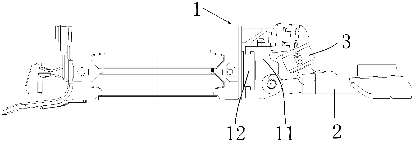
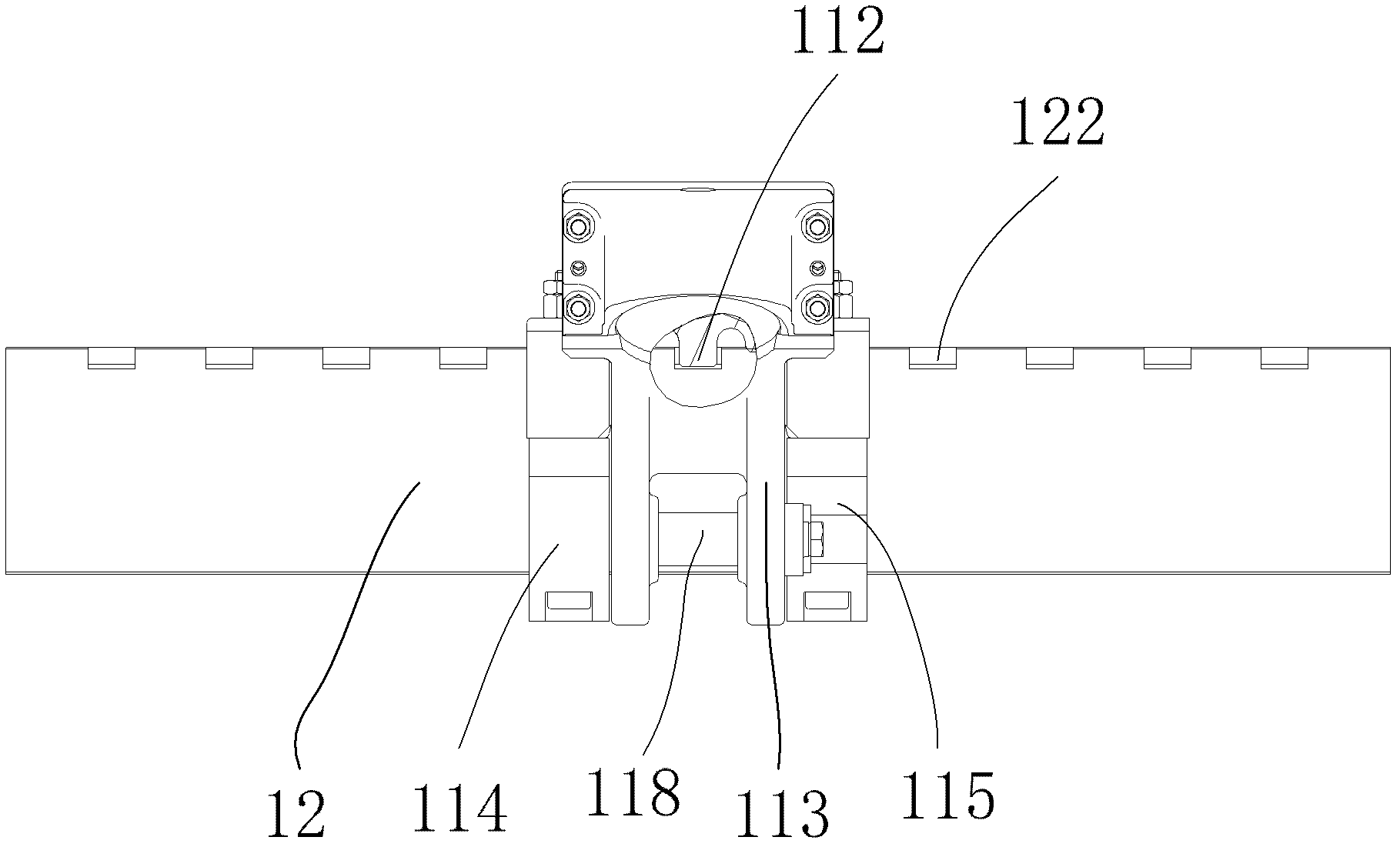
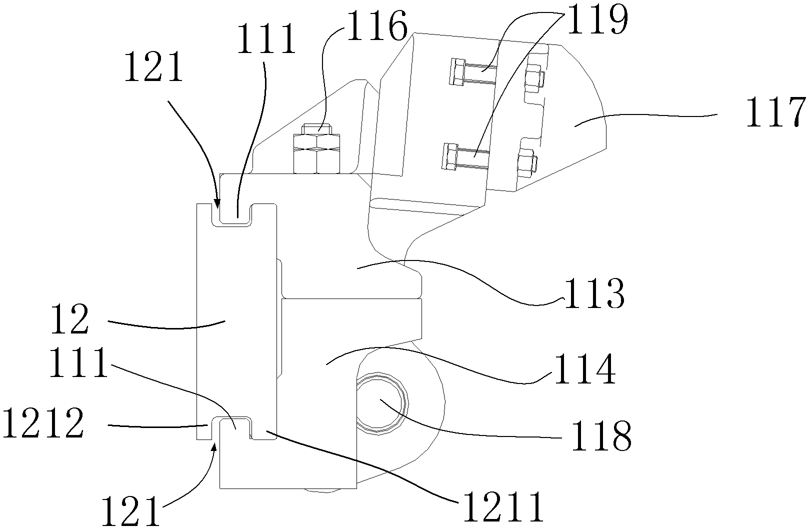
[0027] Such as Figure 1 to Figure 6 As shown, an embodiment of the movable moving device of the present invention is given, wherein, figure 1 It is a schematic diagram of the position of the movable pushing device used on the coal mining machinery; figure 2 It is a schematic diagram of the front view o...


PUM


Abstract

The invention provides a movable pushing device used for a coal mining machine. The movable pushing device comprises a movable pushing seat and a guide device, wherein the guide device is fixed on a body of the coal mining machine, the movable pushing seat is installed on the guide device, sliding teeth of the movable pushing seat are matched with sliding chutes of the guide device, clamping teeth of a body of the movable pushing seat are matched with clamping grooves of the guide device, one end of a height adjustment cylinder is connected with a movable pushing seat through a gland of the height adjustment cylinder, the other end of the height adjustment cylinder is hinged with a pushing cylinder, one end of the pushing cylinder is hinged with the movable pushing seat, and the other end of the pushing cylinder is hinged on a hydraulic support. The invention further provides the coal mining machine equipped with the movable pushing device. According to the technical scheme of the movable pushing device and the coal mining machine, the movable pushing seat can move along the guide device and be stopped when moving to a required position, therefore the requirement of safe support after the change of the width of working faces can be satisfied, and the safety is improved.

Description

technical field [0001] The present invention relates to a coal mining machine, more specifically, to a movable moving device used on the coal mining machine. The present invention also relates to a coal mining machine including the above-mentioned movable moving device, especially a coal plow. Background technique [0002] At present, the pushing devices of coal mining machinery are all fixed pushing devices, the patent number of which is CN201020288246, and the patent titled "Scraper Conveyor Middle Groove Baffle Side with Pushing Connection Structure" discloses a patent with The baffle side of the middle trough of the scraper conveyor with a push connection structure is integrally cast with lugs on the side of the baffle, and the push lugs connected to the hydraulic support are fixed by connecting with the lug pins of the side of the baffle, which belongs to Fixed moving structure. The patent number is CN200620120288, and the patent titled "Scraper Conveyor Coal Conveyor ...

Claims


Application Information

Patent Timeline
Patent Type & Authority Applications(China)
IPC IPC(8): E21C35/20E21C35/08E21C27/32
Inventor 宋永刚张松林张彦国
Owner SANY HEAVY EQUIP
Why Eureka
Try Eureka