
Variable-speed oil cylinder system

A technology of oil cylinder and oil cylinder seat, which is applied in fluid pressure actuators, servo motor components, mechanical equipment, etc. It can solve the problems of poor control effect, complex structure of variable speed oil cylinder, high failure rate of operation, etc., and achieve cost reduction, economy and energy saving Considerable benefit, simple control effect

Inactive Publication Date: 2012-09-19
SHANXI GAOHANG HYDRAULIC
View PDF9 Cites 2 Cited by
  • Summary
  • Abstract
  • Description
  • Claims
  • Application Information

AI Technical Summary

Problems solved by technology

[0003] The invention designs a variable speed oil cylinder system, which solves the problems of the current variable speed oil cylinder with complex structure, high operation failure rate and poor control effect

Method used


Image

  • Variable-speed oil cylinder system
  • Variable-speed oil cylinder system

Examples


Embodiment Construction

[0009] The present invention will be further described below in conjunction with accompanying drawing.

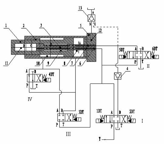
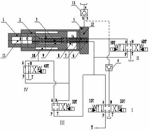
[0010] Refer to attached figure 1 , the transmission cylinder system of the present invention includes a cylinder base 5, a cylinder 2 fixed on the cylinder base, and a piston 1 in the cylinder. The rod body of the piston 1 is a hollow cavity, and a control adjustment rod 3 is fixed on the oil cylinder seat 5. The control adjustment rod 3 penetrates into the hollow cavity of the piston 1, and the piston 1, the cylinder barrel 2, the control adjustment rod 3 and the oil cylinder Four oil chambers are formed between the seats 5, respectively the first oil chamber 8 formed between the piston 1 and the cylinder seat 5, the second oil chamber 9 formed between the outer wall of the control adjustment rod 3 and the inner wall of the hollow chamber of the piston 1, The third oil chamber 10 formed between the outer wall of the piston 1 and the inner wall of the cylinder barrel 2 an...


PUM


Abstract

A variable-speed oil cylinder system includes an oil cylinder seat, a cylinder barrel fixed on the oil cylinder seat, and a piston placed in the cylinder barrel, wherein a control adjusting lever is fixed at the center of the oil cylinder seat, penetrates the front part of the piston, and is placed in a cavity of the piston; four oil chambers with different stressed areas are arranged among the oil cylinder seat, the piston, the cylinder barrel and the control adjusting lever; a first oil tube and a second oil tube are arranged on the control adjusting lever, wherein the first oil tube is communicated with the fourth oil chamber, and the second oil tube is communicated with the second oil chamber; and the variable-speed oil cylinder system is further equipped with four reversing valves, a pilot operated check valve and a check valve. According to the product provided by the invention, through the integration of the combination of the oil cylinder and the system, the oil cylinder is correspondingly provided with four different gradually increased active areas under different pressure along with the pressure variation, so that the best fit of output force and speed of the oil cylinder is realized, and a variable displacement mechanism of a high-speed rotation pair is radically avoided in the design; besides, the switching is full automatic during the entire process, and no limitation of stroke exists; and the control is simple, and the cost is greatly reduced therewith.

Description

technical field [0001] The invention relates to an oil cylinder system, in particular to an oil cylinder system whose operating speed can be changed as the load changes. Background technique [0002] Under many working conditions in the prior art, the oil cylinder is required to increase the thrust as the load increases and the speed decreases during the entire stroke. The previous technology uses a constant power variable pump to achieve complex structure and high cost. Because the pump The variable mechanism of the pump frequently changes under the side effect of high-speed rotation, and the failure rate of the pump is very high, which shortens the service life and affects the operation of the entire system. And it just reduces the time spent running idle at start-up. It cannot be used for the whole process of system operation. Contents of the invention [0003] The invention designs a variable speed oil cylinder system, which solves the problems of the current variabl...

Claims


Application Information

Patent Timeline
Patent Type & Authority Applications(China)
IPC IPC(8): F15B15/00F15B13/04
Inventor 王朝林
Owner SHANXI GAOHANG HYDRAULIC
Learn More