Two-wheeled motor vehicle

A technology for automatic two-wheeled vehicles and rear wheels, which is applied to bicycle accessories, bicycle control systems, axle suspension devices, etc. power, and the effect of improving design

Inactive Publication Date: 2005-11-23
YAMAHA MOTOR CO LTD +1
View PDF0 Cites 0 Cited by
  • Summary
  • Abstract
  • Description
  • Claims
  • Application Information

AI Technical Summary

Problems solved by technology

[0006] However, when such an upright installation is performed, since the spring switching mechanism is located below the shock absorber, it may interfere with the rear wheel sprocket and the muffler, making it difficult to secure an arrangement space for the switching mechanism and reducing the degree of freedom in design.
In addition, when the spring characteristic switching mechanism and the intermediate spring support part are arranged on the piston rod side, the stroke amount of the shock absorber is limited by the structure

Method used


Image

  • Two-wheeled motor vehicle
  • Two-wheeled motor vehicle
  • Two-wheeled motor vehicle

Examples


Embodiment Construction

[0060] Embodiments of the present invention will be described in detail below with reference to the accompanying drawings.

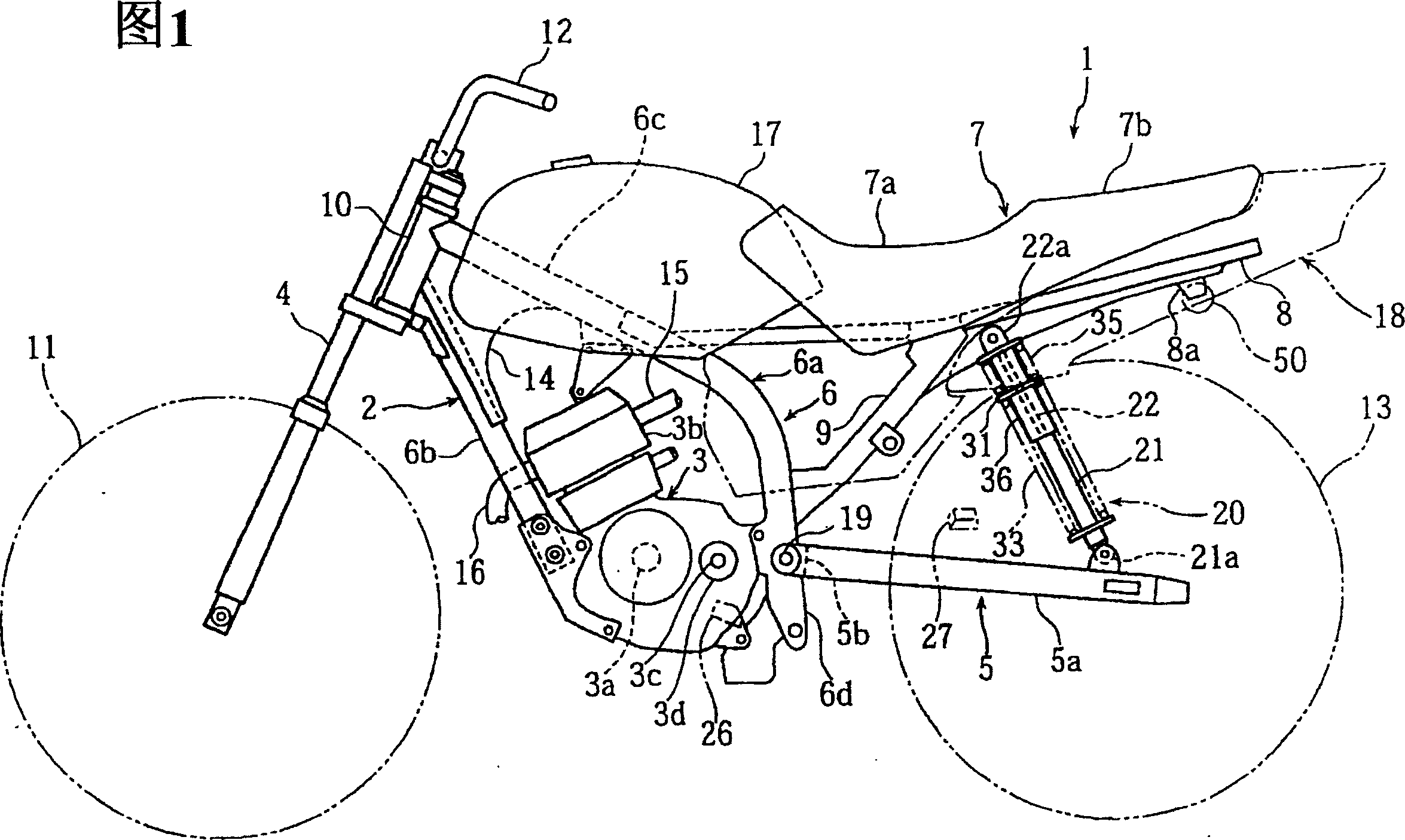
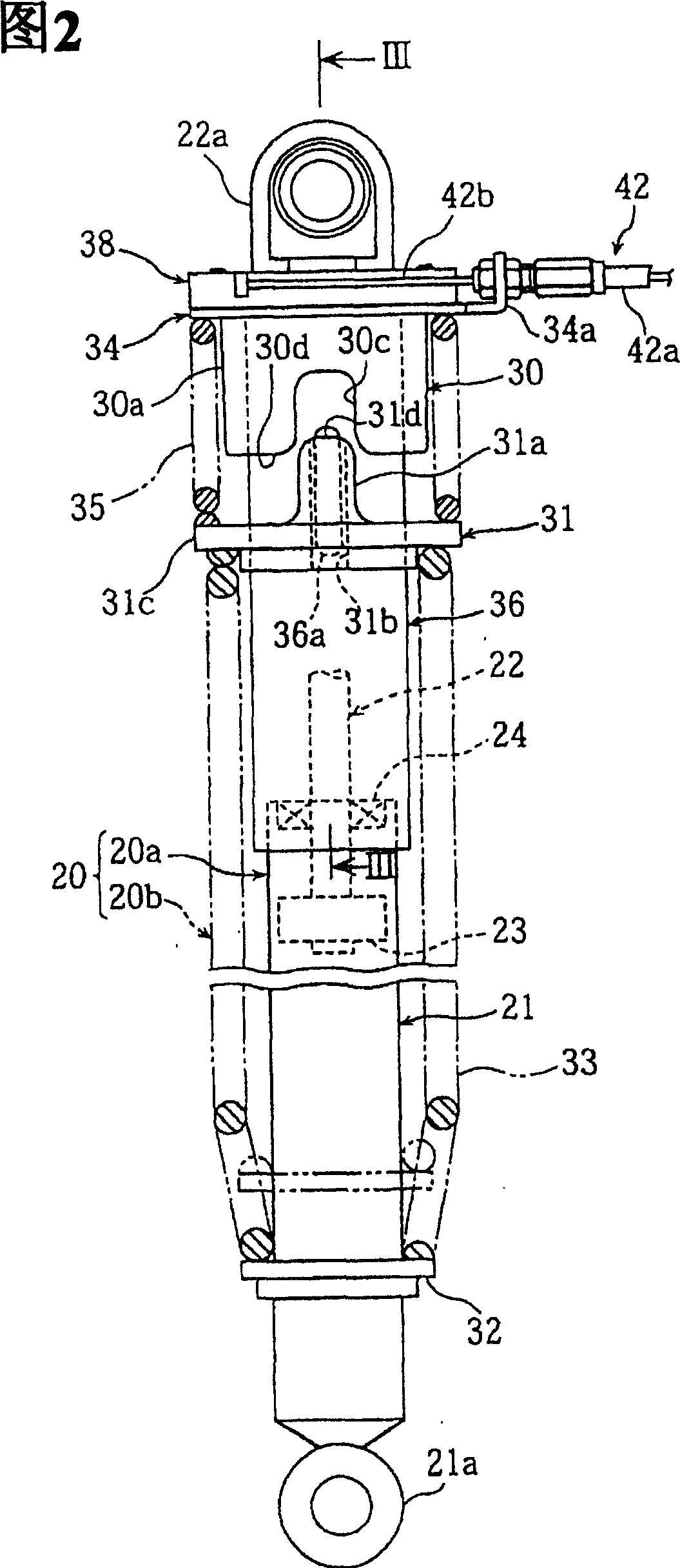
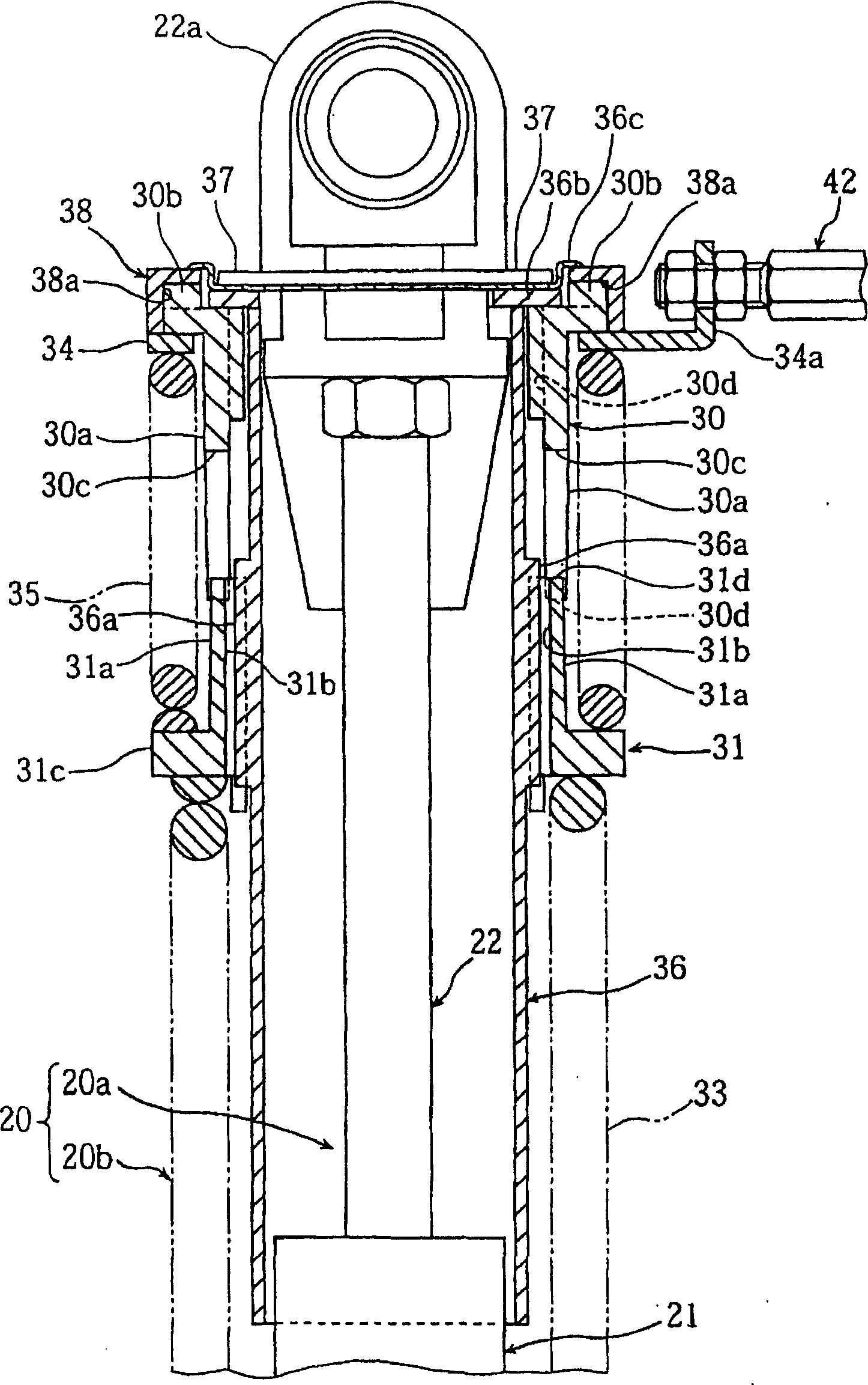
[0061] Figure 1~ Figure 13 It is used to explain the motorcycle according to the first embodiment of the present invention; FIG. 1 is a side view of a motorcycle provided with a rear wheel buffer device, and FIG. 2 is a front view of a buffer, image 3 It is a cross-sectional view of the spring characteristic switching mechanism of the buffer (the III-III line cross-sectional view of FIG. 2 ), and FIG. 4 is a top view of the operating part of the switching mechanism, Figure 5 is a partial sectional view of the operating part, Figure 6 is a perspective view of the buffer, Figure 7 is a perspective view of the dust cover, Figure 8 is a perspective view of the middle spring bracket part, Figure 9 is the perspective view of the cam, Figure 10 is the perspective view of the upper spring support, Figure 11 is the perspective view of the annular plate,...


PUM


Abstract

A piston rod (22) is connected to a vehicle body frame so as to be located on the upper side of a cylinder (21), a cover (36) is installed on the piston rod (22) so as to cover an outer peripheral portion of the piston rod, and an intermediate spring-receiving member (31) and a cam (spring characteristics-switching mechanism)(30) are arranged outside the cover (36).

Description

technical field [0001] The invention relates to an automatic two-wheel vehicle including a rear wheel buffer device. Background technique [0002] In motorized two-wheel vehicles, rear wheel cushioning devices are sometimes included to ensure ride comfort and handling stability even when the weight of rear occupants or cargo load changes. [0003] As this kind of rear wheel buffer device, the following buffer device has been proposed in the past: the intermediate spring support member is installed movably in the axial direction on the cylinder in which the piston rod is inserted, and the main coil spring is arranged on the intermediate spring support member and the piston. Between the spring supports on the rod side, and an auxiliary coil spring is arranged between the intermediate spring support part and the cylinder side spring support, thereby constituting a buffer; and a switching mechanism is provided for switching the intermediate spring support part To obtain the com...

Claims


Application Information

Patent Timeline
Patent Type & Authority Applications(China)
IPC IPC(8): B62J25/00B62K23/06B62K25/10
CPCB62K23/06B62J25/00B62K25/10B62J25/06
Inventor 荒木敏夫小野惣一
Owner YAMAHA MOTOR CO LTD
Why Eureka
Try Eureka