Split type air foot

A split-type, air-footed technology, applied to physical instruments, bearings, shafts, etc., can solve problems such as air flotation loss of function, and achieve the effect of high air flotation requirements and high rigidity

Active Publication Date: 2012-09-19
SHANGHAI MICRO ELECTRONICS EQUIP (GRP) CO LTD
View PDF5 Cites 19 Cited by
  • Summary
  • Abstract
  • Description
  • Claims
  • Application Information

AI Technical Summary

Problems solved by technology

The characteristic of the one-piece air foot structure is that to increase the air flotation stiffness of the air foot, it is necessary to increase the air buoyancy force N and the vacuum preload F at the same time, and increasing the vacuum preload F will cause the air foot plate to 1 bends in the middle (e.g. figure 2 Shown by the dotted line in ), since the air film thickness δ of the air flotation is generally only a few microns to more than ten microns, therefore, when the bending amount σ of the air foot plate 1 is too large, the middle part of the air foot plate 1 and the When the platform 4 is in contact, the movement of the air foot will produce mechanical friction, making the air flotation useless

Method used


Image

  • Split type air foot
  • Split type air foot
  • Split type air foot

Examples


Embodiment Construction

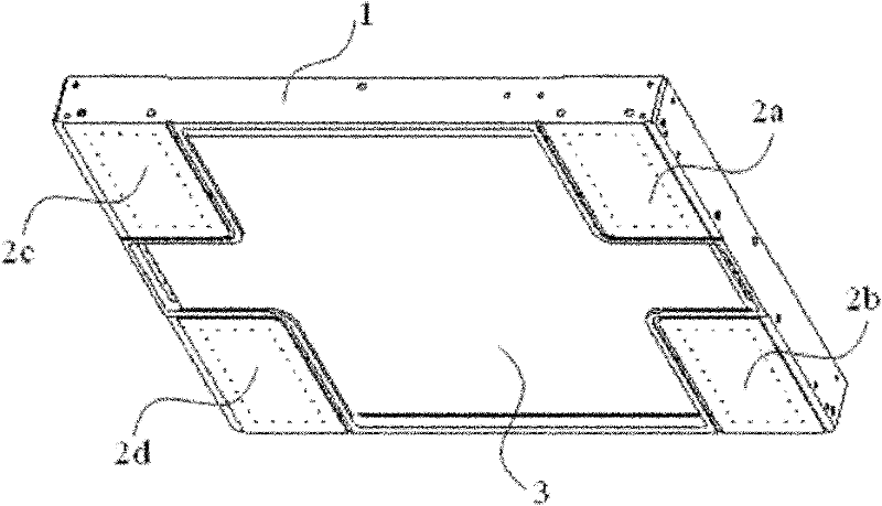
[0028] The following will combine Figure 3 ~ Figure 7 The split type air foot of the present invention is further described in detail.

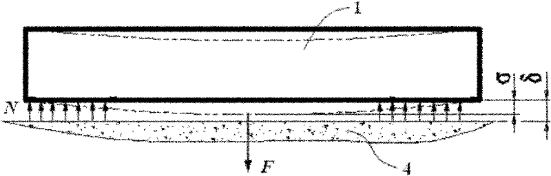
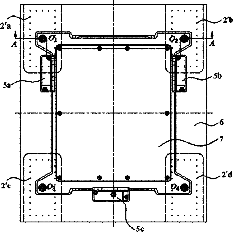
[0029] The split air foot of the present invention includes an air foot plate, an air floating structure arranged at the bottom of the air foot plate, and a vacuum preload structure arranged on the air foot plate, and the vacuum preload structure is connected to the air foot plate The air foot plate is split-connected, and the connection point between the vacuum preload structure and the air foot plate is on the same straight line perpendicular to the platform as the center of the air flotation structure, and the vacuum preload force The position of the bottom surface of the structure is higher than the position of the bottom surface of the air foot plate, and a vacuum cavity is formed between the bottom surface of the vacuum pre-tightening force structure and the bottom surface of the air foot plate.

[0030] The split type air foot of the...


PUM


Abstract

A split type air foot provided by the invention is used for supporting a motion stage to move on a platform without friction. The air foot comprises an air foot plate, an air floating structure disposed at a bottom of the air foot plate, and a vacuum pre-tightening structure disposed on the air foot plate, wherein the vacuum pre-tightening structure is connected with the air foot plate in a split style. By separating the air-floating structure from the vacuum pre-tightening structure, bend and deformation of the air foot plate when a pre-tightening force is applied can be avoided, so that the air-floating area is not influenced.

Description

technical field [0001] The invention relates to microelectronic equipment, in particular to a split air foot. Background technique [0002] The air foot is the key component to provide air bearing support for the precision motion table to ensure the frictionless movement of the motion table on the platform (usually a marble platform), which includes an air flotation structure and a vacuum preload structure. [0003] figure 1 Shown is a square air foot of the prior art, the four corners of the bottom surface of the air foot plate 1 of the square air foot are air floating structures 2a, 2b, 2c and 2d, and the center is a vacuum preload structure 3. The air flotation structures 2a, 2b, 2c and 2d and the vacuum pretensioning force structure 3 are processed into one by the air foot plate 1, as figure 2 shown. [0004] Such as figure 2 As shown, when the air foot is working, the air flotation structures 2a, 2b, 2c and 2d are fed with positive pressure gas to form an air film...

Claims


Application Information

Patent Timeline
Patent Type & Authority Applications(China)
IPC IPC(8): F16C32/06
CPCF16C29/025G03F7/70816F16C32/06F16C32/0614G03F7/707G03F7/70783F16C32/0674F16C2370/20F16C2370/00
Inventor 李进春齐芊枫方洁郑椰琴夏海吴立伟
Owner SHANGHAI MICRO ELECTRONICS EQUIP (GRP) CO LTD
Why Eureka
Try Eureka