Method for measuring optical power, optical line terminal and optical network unit

A technology of optical line terminal and optical network unit, which is applied in the field of communication and can solve the problems of wasting bandwidth and affecting the normal operation of ONU.

Active Publication Date: 2010-10-06
HUAWEI TECH CO LTD
View PDF4 Cites 19 Cited by
  • Summary
  • Abstract
  • Description
  • Claims
  • Application Information

AI Technical Summary

Problems solved by technology

Therefore, in the prior art, the method of using the DBA module to allocate a large bandwidth to the ONU to be tested for burst optical power measurement will cause a huge waste of bandwidth and affect the normal operation of other ONUs at the same time.

Method used


Image

  • Method for measuring optical power, optical line terminal and optical network unit
  • Method for measuring optical power, optical line terminal and optical network unit
  • Method for measuring optical power, optical line terminal and optical network unit

Examples


Embodiment Construction

[0030] In order to facilitate those skilled in the art to understand and implement the present invention, the embodiments of the present invention are now described with reference to the accompanying drawings. Here, the exemplary embodiments of the present invention and the description thereof are used to explain the present invention, but not as a limitation to the present invention.

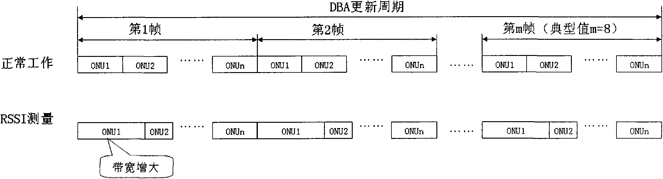
[0031] The optical power measurement method provided by the embodiment of the present invention is applied to a Gigabit passive optical network (Gigabit passive Optical Network, GPON) that includes an OLT and multiple ONUs for point-to-multipoint communication. The optical power of the ONU is measured by the OLT. The measurement provides a basis for analyzing the performance of the link between the OLT and the ONU under test.

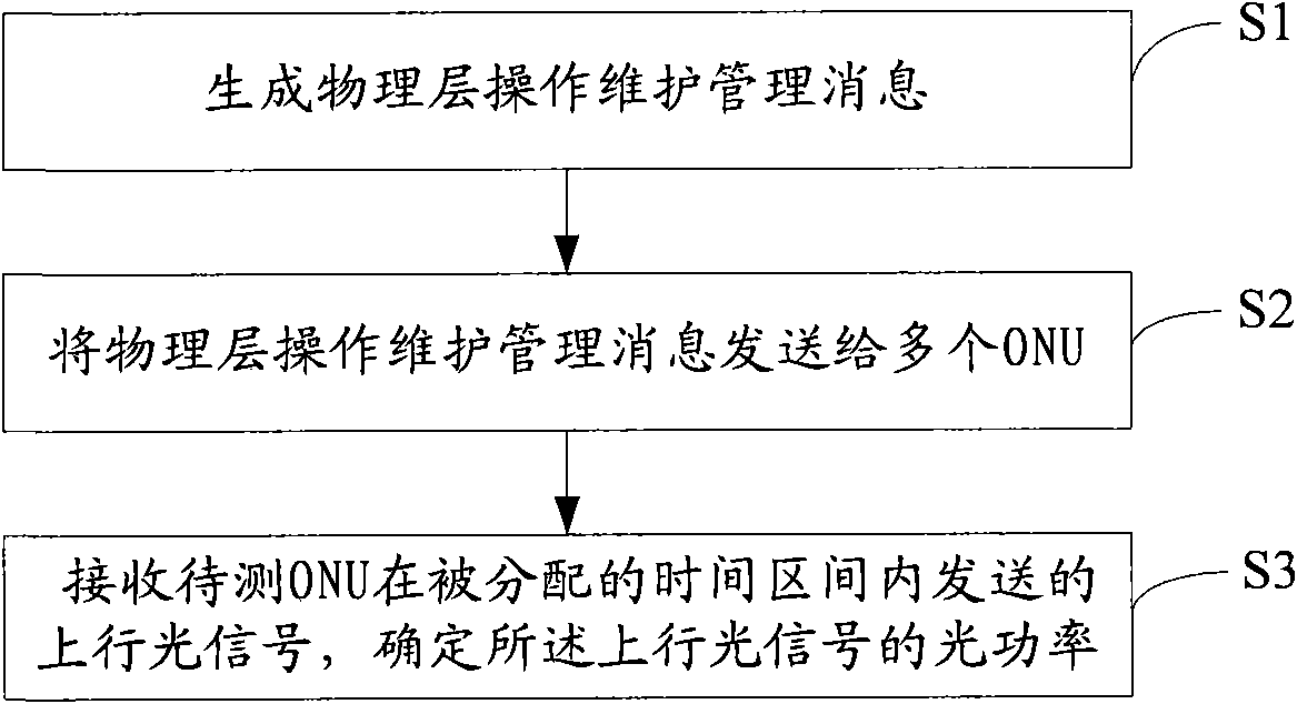
[0032] The flow chart of a method for measuring optical power in the embodiment of the present invention is as follows: figure 2 As shown, the method includes:

[0033] Step ...


PUM


Abstract

The embodiment of the invention discloses a method for measuring optical power, an optical line terminal and an optical network unit, belonging to the communication field. The method comprises the following steps: generating physical layer operations and maintenance (PLOAM) information which comprises identification of ONUs to be measured and information of time intervals distributed to the ONUs to be measured and used for transmitting upstream optical signals; transmitting the PLOAM information to a plurality of ONUs; receiving the upstream optical signal transmitted by ONUs to be measured in the distributed time intervals; and detecting the received upstream optical signals and determining the optical power of the upstream optical signals. The invention avoids bandwidth wastage caused by bandwidth for optical power detection assigned by a DBA module to the ONUs to be measured in the process of optical power detection in the prior art.

Description

Technical field [0001] The present invention relates to the field of communications, in particular to a method for measuring optical power, an optical line terminal and an optical network unit. Background technique [0002] With the gradual decline in the cost of optical fiber transmission, the optical fiber of the access network is an inevitable development trend. The access network segment that represents the "last mile" part has requirements for ultra-low cost, simple structure, and easy implementation, which brings great challenges to technical implementation. The PON (Passive Optical Network, passive optical network) uses passive components and is the most promising technology for realizing broadband optical access networks. [0003] The passive optical network is usually composed of an optical line terminal (Optical Line Terminal, OLT) located in the central office and a series of optical network units (ONU) located in the user's premises. Optical Distribution Network (ODN)...

Claims


Application Information

Patent Timeline
Patent Type & Authority Applications(China)
IPC IPC(8): H04B10/08H04Q11/00H04B10/077
CPCH04B2210/072H04B10/0775H04Q2011/0081H04Q11/0067H04Q2011/0083H04J3/1694H04B10/0773H04B10/0779
Inventor 丁平董英华梁选勤吴广东
Owner HUAWEI TECH CO LTD
Why Eureka
Try Eureka