Device and method for detection, rejection and docking of rigid electric ignition charge

A technology of a igniter head and a docking device, which is applied to fuzes, weapon accessories, offensive equipment, etc., can solve the problem that the resistance of the rigid electric igniter head cannot be detected online, and the resistance of the electric igniter element is unstable and lacks integrity. Connection discontinuity and other problems, to achieve the effects of good ignition synchronization, improved seismic resistance, and stable resistance

Active Publication Date: 2015-07-29
GUANGDONG HONGDA BLASTING +1
View PDF5 Cites 0 Cited by
  • Summary
  • Abstract
  • Description
  • Claims
  • Application Information

AI Technical Summary

Problems solved by technology

[0002] Please refer to figure 1 , at present, in the production of the electric ignition element of the detonator, the butt joint process of the rigid electric ignition powder 1 and the foot wire 2 is completed by the crimping method. Poor; and in the production process of the existing rigid electric igniter, the resistance of the rigid electric igniter cannot be detected online and the rigid electric igniter with unqualified resistance cannot be automatically eliminated online, but only after the rigid electric igniter is produced. , manually detect the resistance of the rigid electric igniter and reject the unqualified rigid electric igniter. It can be seen that in the production process of the existing rigid electric igniter, there is a lack of overall connection and discontinuity between the various processes. Therefore, it is difficult to improve Productivity

Method used


Image

  • Device and method for detection, rejection and docking of rigid electric ignition charge
  • Device and method for detection, rejection and docking of rigid electric ignition charge
  • Device and method for detection, rejection and docking of rigid electric ignition charge

Examples


Embodiment Construction

[0033] The present invention will be further described in detail below in conjunction with the embodiments and the accompanying drawings, but the embodiments of the present invention are not limited thereto.

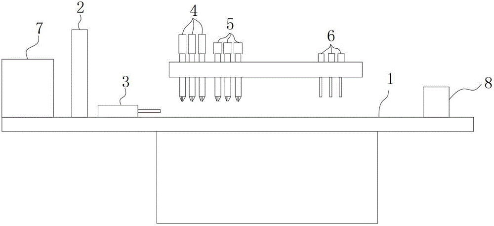
[0034] Please refer to figure 2 , image 3 , the present invention provides a detection, removal and docking device for rigid electric ignition powder, which includes: workbench 1, crimping machine 2, stepping mechanism 3, 3 sets of rigid electric ignition powder resistance automatic detection machine 4, 3 A rejecting machine 5, three hot-press welding machines 6, a PLC (not shown), a computer 7 and an ejection device 8.

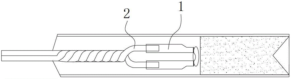
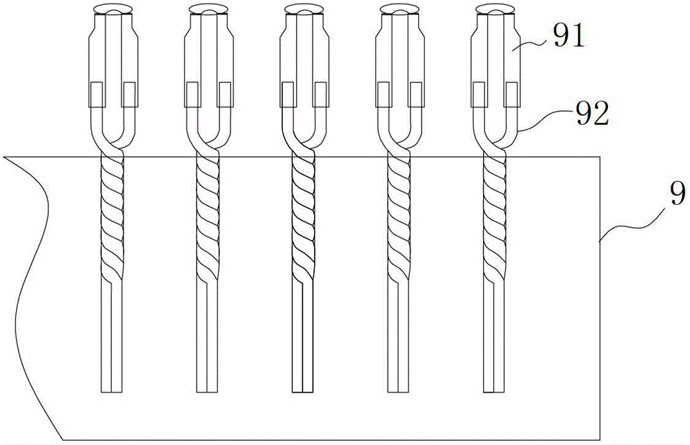
[0035] The crimping machine 2 is arranged on the workbench 1 and is used for crimping the rigid electric ignition charge head 91 on the leg wire 92 .

[0036] The stepping mechanism 3 is a mold pushing cylinder, which is used to push the rigid electric ignition powder head module 9 to move.

[0037] The 3 sets of automatic detection machines 4 for ...


PUM


Abstract

The invention relates to the manufacture field of rigidity electric ignition powder heads of industrial electric detonators and discloses a device for detection, rejection and butt connection of the rigidity electric ignition powder heads. The device comprises a stepping mechanism, a rigidity electric ignition powder head resistance automatic detection machine, a rejection machine, a hot press welder, a programmable logic controller (PLC) and a computer. The rigidity electric ignition powder head resistance automatic detection machine is provided with a resistance measuring instrument, and a probe is respectively connected with two poles of the resistance measuring instrument. The rejection machine is arranged on the conveying route of the stepping mechanism and located at the back of the rigidity electric ignition powder head resistance automatic detection machine. The hot press welder is arranged on the conveying route of the stepping mechanism and located at the back of the rejection machine. The computer is connected with the rigidity electric ignition powder head resistance automatic detection machine, a rejection cylinder of the rejection machine and the hot press welder through the PLC. The device is high in production efficiency and capable of producing rigidity electric ignition elements with stable resistance and good shockproof capability.

Description

technical field [0001] The invention relates to the field of manufacturing rigid electric ignition powder heads of industrial electric detonators, in particular to a device and method for detecting, rejecting and docking rigid electric ignition powder heads. Background technique [0002] Please refer to figure 1 , at present, in the production of the electric ignition element of the detonator, the butt joint process of the rigid electric ignition powder 1 and the foot wire 2 is completed by the crimping method. Poor; and in the production process of the existing rigid electric igniter, the resistance of the rigid electric igniter cannot be detected online and the rigid electric igniter with unqualified resistance cannot be automatically eliminated online, but only after the rigid electric igniter is produced. , manually detect the resistance of the rigid electric igniter and reject the unqualified rigid electric igniter. It can be seen that in the production process of the ...

Claims


Application Information

Patent Timeline
Patent Type & Authority Patents(China)
IPC IPC(8): F42C21/00F42C17/00
Inventor 郑炳旭柯育宏陈鸿龙谭文锋王成李战军韦锦初
Owner GUANGDONG HONGDA BLASTING
Why Eureka
Try Eureka