Axial force sensor

An axial force sensor and stress groove technology, applied in the field of force sensors, can solve the problems of poor anti-eccentric load capacity, easy damage to the sensor, large volume, etc. low effect

Active Publication Date: 2012-09-19
ZHONGHANG ELECTRONICS MEASURING INSTR
View PDF6 Cites 13 Cited by
  • Summary
  • Abstract
  • Description
  • Claims
  • Application Information

AI Technical Summary

Problems solved by technology

However, the force sensors that can be used in the prior art are only column type, spoke type, cylinder type and shear beam type. Although these types of sensors can be used to detect the magnitude of axial force, their problems are 1. Large size, limited by the installation space, difficult to install; 2. Under the condition of large pre-tightening force, the detection stability of the sensor is reduced; 3. After the connection point is installed, the sensor itself will act as the force application axis and the connection axis Or a part of the whole connection formed by the stressed parts, under the action of a large pre-tightening force on the whole connection, the safety factor of the sensor decreases with the increase of the pre-tightening force, and due to the poor anti-eccentric load ability, the sensor is extremely Easily damaged, once the sensor is abnormal or damaged, it will directly affect the safety of the connection as a whole and destroy the integrity of the connection as a whole

Method used


Image

  • Axial force sensor
  • Axial force sensor
  • Axial force sensor

Examples


Embodiment Construction

[0025] The present invention will be further described below in conjunction with accompanying drawing.

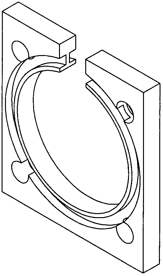
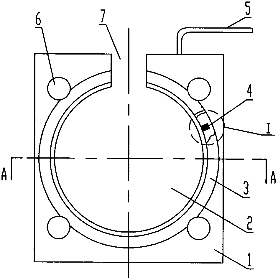
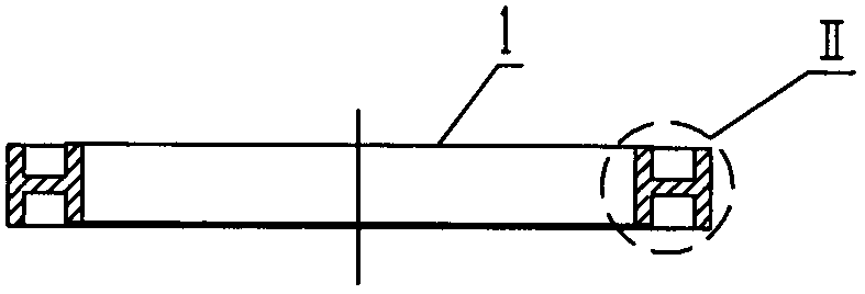
[0026] Such as Figure 1-5 As shown, the axial force sensor of the present invention includes an elastic body 1. The elastic body 1 is a flat plate. There is a shaft passing hole 2 in the middle of the plate surface, and a plurality of bolt passing holes 6 are evenly distributed around the periphery. The overall shape is similar to a flange. The disk gasket has an annular stress groove 3 on the positive surface of the elastic body 1 near the shaft through hole 2, and an annular stress groove 3 on the reverse surface of the elastic body 1, two positive and negative The stress grooves 3 have the same diameter and are concentric with the shaft through hole 2 . The resistance strain gauges 4 are attached to the stress grooves 3 . All the resistance strain gauges 4 form a Wheatstone balance bridge and are connected to external electrical appliances through cables 5 .

[0027] S...


PUM


Abstract

The invention discloses an axial force sensor, which comprises an elastic body, wherein the elastic body is of a flat plate shape; an axis penetration through hole is formed in the middle of the plate surface; a plurality of bolt penetration holes are formed at the periphery of the elastic body; the whole shape of the elastic body is similar to that of a gasket of a flange disk; an annular stress slot concentric with the shaft axis penetration through hole is formed on each of the front plate surface and the rear plate surface of the elastic body, and the diameters of the annular stress slots are equal substantially; the stress slots are close to the axis penetration through hole; resistance strain gauges are attached to the stress slots and form a WheatStone balance bridge which is connected with an external electric appliance. The axial force sensor is low in height, small in size and similar to the gasket in the shape, can be conveniently assembled between the force applying shaft of the appliance and the flange disk or a stressed part at the connection shaft end of the appliance, is damaged difficultly, and is firm and high in lateral and unbalance loading resistance; and when the sensor is stressed by an axial load, part of the elastic body in each stress slot is effectively deformed, so that an axial force value can be sensitively and accurately detected.

Description

technical field [0001] The invention relates to a force sensor, in particular to a sensor installed between shafts, shafts and force-bearing parts for detecting axial force. Background technique [0002] In industrial control, the force application shaft of the equipment is usually connected in the form of a flange to the connecting shaft or the force receiving part, and the axial force detection between the two is basically completed by a force sensor. However, the force sensors that can be used in the prior art are only column type, spoke type, cylinder type and shear beam type. Although these types of sensors can be used to detect the magnitude of axial force, their problems are 1. Large size, limited by the installation space, difficult to install; 2. Under the condition of large pre-tightening force, the detection stability of the sensor is reduced; 3. After the connection point is installed, the sensor itself will act as the force application axis and the connection ax...

Claims


Application Information

Patent Timeline
Patent Type & Authority Applications(China)
IPC IPC(8): G01L1/22
Inventor 刘鹏张志刚王小岗汪洋张树进董宏利孙莉
Owner ZHONGHANG ELECTRONICS MEASURING INSTR
Why Eureka
Try Eureka