
A loading device for structural strength test of aircraft wing crane engine

A loading device and structural strength technology, which is applied in the direction of engine testing, machine/structural component testing, measuring devices, etc., can solve problems such as not considering the vertical displacement of the wing, affecting test assessment results, loading distortion, etc., to achieve The results of the assessment are accurate and reliable

Active Publication Date: 2014-10-22
XIAN AIRCRAFT DESIGN INST OF AVIATION IND OF CHINA
View PDF5 Cites 0 Cited by
  • Summary
  • Abstract
  • Description
  • Claims
  • Application Information

AI Technical Summary

Problems solved by technology

At present, during the strength test of the wing crane engine, the force and moment on the engine are mainly applied by the five-way actuator. This load application method does not consider the vertical displacement of the wing, which will lead to a large error, especially for the When the engine is loaded on the outer wing of a large aircraft, the loading distortion is caused, which affects the test results

Method used


Image

  • A loading device for structural strength test of aircraft wing crane engine
  • A loading device for structural strength test of aircraft wing crane engine
  • A loading device for structural strength test of aircraft wing crane engine

Examples


Embodiment Construction

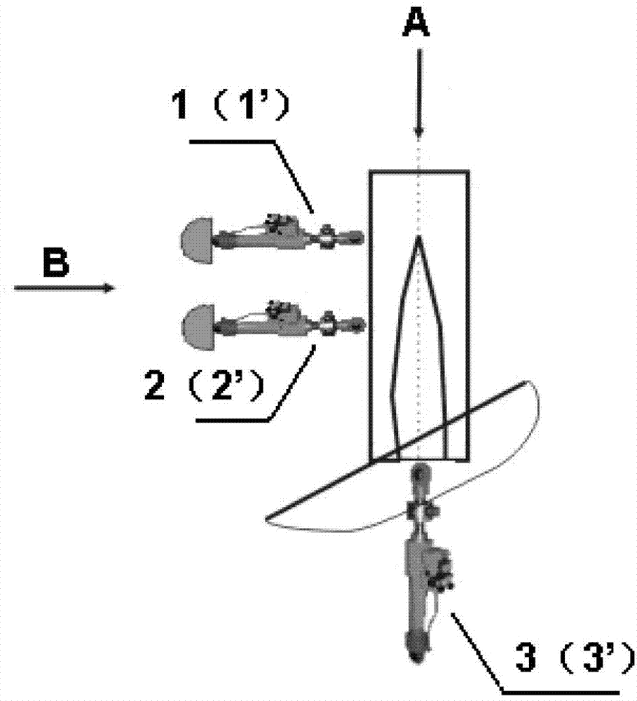
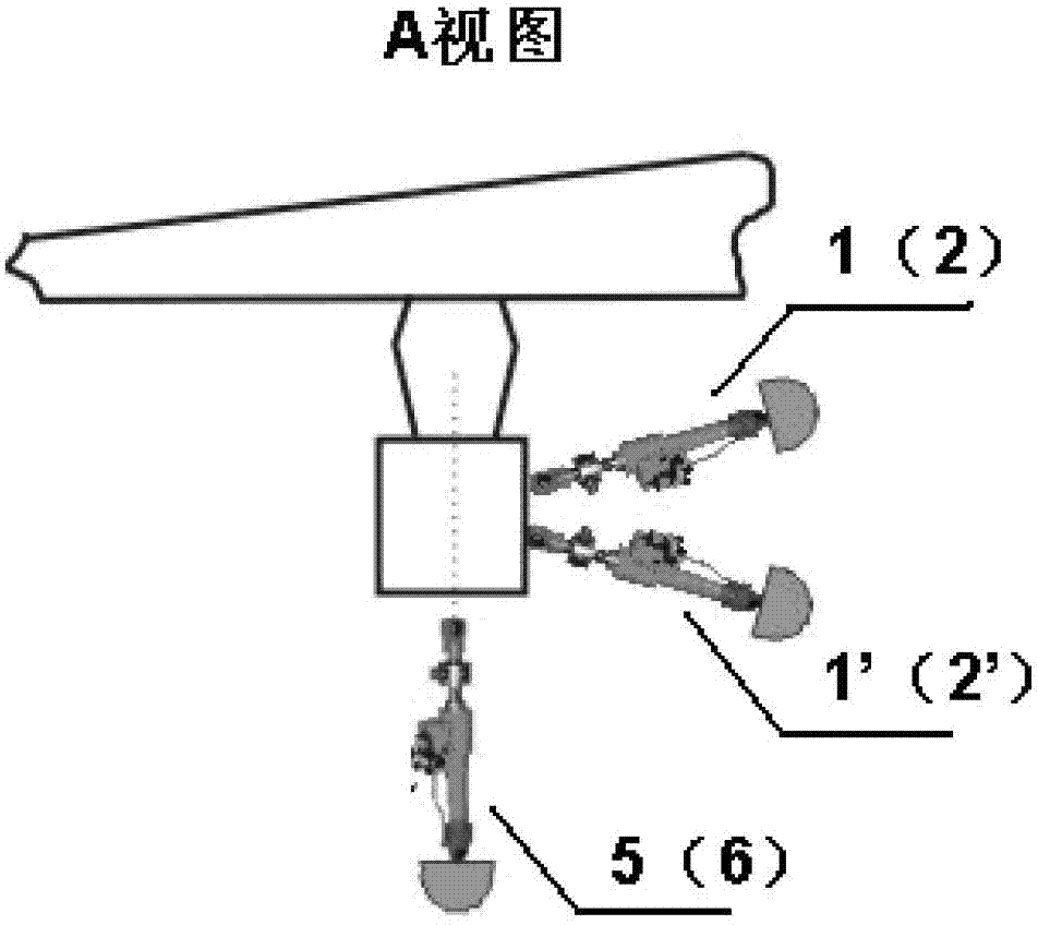
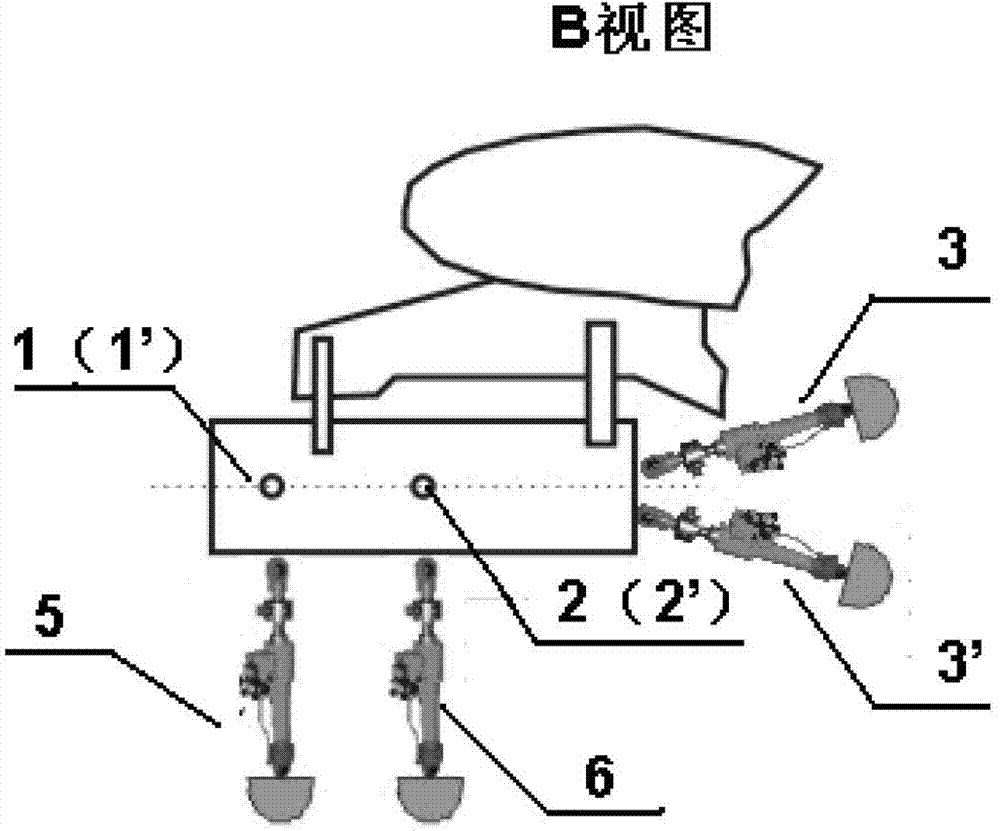
[0012] The present invention will be described in further detail below. see figure 1 , figure 2 and image 3 , the loading device for the structural strength test of the aircraft wing crane engine, including side front loading actuators 1, 1', side rear loading actuators 2, 2', front actuators 3, 3', lower actuators 5, 6, It is characterized in that the loading device includes two side front loading actuators 1, 1', two side rear loading actuators 2, 2', two front actuators 3, 3', and lower actuators 5, 6 , the two side front loading actuators 1, 1' are located on one side of the engine, and the loading points of the two side front loading actuators 1, 1' are connected at the center of gravity of the engine for applying side loads on the engine. The front loading actuators 1, 1' are located in the same plane, which is perpendicular to the engine axis and the horizontal plane, and the two side front loading actuators 1, 1' form an included angle of 30 degrees. With the inc...


PUM


Abstract

The invention belongs to an aircraft strength testing technology and relates to a structural strength test loading device for an aircraft wing-mounted engine. The structural strength test loading device comprises side front loading actuating cylinders, side rear loading actuating cylinders, front actuating cylinders and lower actuating cylinders, and is characterized in that the loading device comprises the two side front loading actuating cylinders, the two side rear loading actuating cylinders, the two front actuating cylinders and the lower actuating cylinders. According to the loading device disclosed by the invention, a course load of the engine is applied through a pair of the actuating cylinders which mutually form the angle, so that the loading device can ensure that the course load can be always positioned along the direction of the axial line of the engine under the condition that the deformation of airfoils occurs during testing; a lateral load of the engine can be applied through the pair of the actuating cylinders which mutually form the angle, so that the loading device can ensure that the lateral load can be always positioned in the horizontal direction under the condition that the deformation of the airfoils occurs; and a hanging lateral load of the engine is applied by the pair of the actuating cylinders which mutually form the angle, so that the loading device can ensure that the lateral load can be always positioned in the horizontal direction under the condition that the deformation of the airfoils occurs. The loading device can ensure the loading precision of the loads of the wing-mounted engine under the condition that the deformation of the airfoils occurs so as to enable a testing check result to be more accurate and reliable.

Description

technical field [0001] The invention belongs to the aircraft strength test technology, and relates to a loading device for the structural strength test of an aircraft wing cradle engine. Background technique [0002] The wing-mounted engine is a commonly used design form for transport aircraft. The engine suspension and its connections need to be verified by strength tests, and the accurate application of engine loads is an important condition for strength verification. At present, during the strength test of the wing crane engine, the force and moment on the engine are mainly applied by the five-way actuator. This load application method does not consider the vertical displacement of the wing, which will lead to a large error, especially for the When the engine is loaded on the outer wing of a large aircraft, it will cause loading distortion, which will affect the test results. Contents of the invention [0003] The object of the present invention is to provide a loading...

Claims


Application Information

Patent Timeline
Patent Type & Authority Patents(China)
IPC IPC(8): G01M15/00
Inventor 王新波宁宇张志楠王继普
Owner XIAN AIRCRAFT DESIGN INST OF AVIATION IND OF CHINA
Learn More