The load loading system and the selection method of the disc spring group used in the reliability test device of the cabin door lock

A test device and loading system technology, which is applied in the direction of spring components, springs, and measuring devices composed of several springs, can solve the problems of large changes in the load of the lock ring and the inability to ensure the loading accuracy of the lock hook, and achieve high loading accuracy Effect

Active Publication Date: 2018-11-16
NORTHWESTERN POLYTECHNICAL UNIV
View PDF14 Cites 0 Cited by
  • Summary
  • Abstract
  • Description
  • Claims
  • Application Information

AI Technical Summary

Problems solved by technology

[0005] The purpose of the present invention is to solve the problem that when the load spring of the existing cabin door lock reliability test device is stretched or compressed, the load on the lock ring changes greatly, and the loading accuracy of the lock hook cannot be guaranteed. A load loading system used in a reliability test device of a cabin door lock and a method for selecting the disc spring group

Method used


Image

  • The load loading system and the selection method of the disc spring group used in the reliability test device of the cabin door lock
  • The load loading system and the selection method of the disc spring group used in the reliability test device of the cabin door lock
  • The load loading system and the selection method of the disc spring group used in the reliability test device of the cabin door lock

Examples


specific Embodiment approach 1

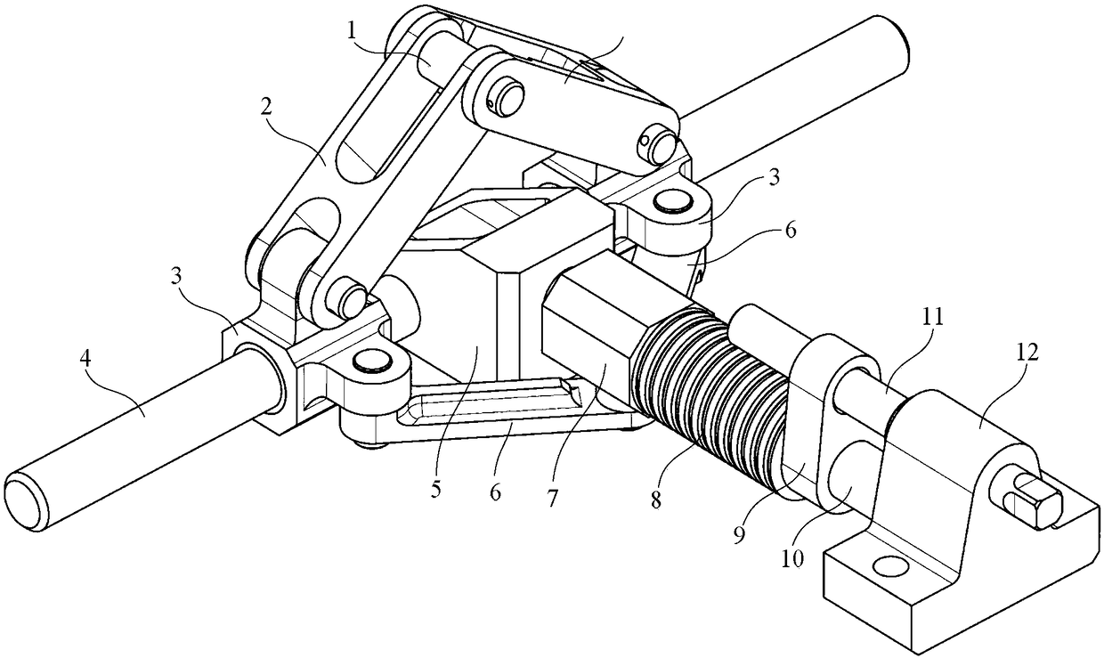
[0048] Specific implementation mode one: the following combination Figure 1 to Figure 5 Describe this embodiment, the load loading system used for the hatch door lock reliability test device described in this embodiment, it includes a lock ring 1, two No. 1 connecting rods 2, two No. 1 sliders 3, and No. 1 guide rails 4 , No. 1 guide rail intermediate joint 5, two No. 2 connecting rods 6, No. 2 slider 7, disc spring group 8, load adjustment block 9, No. 2 guide rail 10, load adjustment lever 11 and No. 2 guide rail joint 12,

[0049] The middle of the No. 1 guide rail 4 is fixedly connected to the No. 1 guide rail intermediate joint 5, and the two No. 1 sliders 3 are arranged on both sides of the No. 1 guide rail intermediate joint 5, and are slidably connected to the No. 1 guide rail 4; One end of the rod 2 is rotatably connected with the lock ring 1 at the same time, the lock ring 1 is located directly above the middle joint 5 of the No. 1 guide rail, and the other ends of ...

specific Embodiment approach 2

[0059] Specific implementation mode two: the following combination Figure 1 to Figure 7 Describe this implementation mode, this implementation mode is realized based on Embodiment 1, and it comprises the following four steps:

[0060] The first step is to determine the initial elastic coefficient k of the disc spring group 8 TH for:

[0061]

[0062] In the formula, F HK2,2 is the load on the second slider 7 when the lock ring 1 is at the highest position; F HK2,1 is the load on the second slider 7 when the lock ring 1 is at the lowest position; V HK2,2 When the lock ring 1 is at the highest position, the distance between the axis of the second slider rotation pair and the axis of the first guide rail; V HK2,1 is the distance between the axis of the No. 2 slider rotating pair and the No. 1 guide rail axis when the lock ring 1 is at the lowest position;

[0063] When the locking ring 1 is in the lowest position, F HK2,1 and the load F on the disc spring group at this ...

specific Embodiment

[0090] Concrete embodiment: in the test process, the ideal load F that lock ring 1 is subjected to SH It is 1500N, and the load error limit in engineering practice is generally 5%. The determination method and process of the relevant parameters of the load loading system are as follows:

[0091] (1) Determine the length L of the No. 1 connecting rod 2 LG1 . According to the movement principle and size parameters of the cabin door lock, the upward movement distance of the lock ring 1 during the locking process is 20mm, that is, V SH,2 -V SH,1 = 20mm. According to the allowable height of the test device, determine the distance V between the axis of the locking ring 1 and the axis of the No. 1 guide rail 4 when it is at the lowest position SH,1 40mm, then V SH,2 is 60mm. According to the position parameters of the bolt holes on the vibrating table surface, determine the left and right width H of the middle joint 5 of the No. 1 guide rail JT is 60mm, the length L of the No...


PUM


Abstract

The invention relates to a load loading system for a hatch lock reliability testing device and a butterfly-shaped spring assembly selecting method of the load loading system, belongs to load loading technologies of a hatch lock, and aims at solving the problems that a load born by a lock ring changes widely when a load loading spring of a present hatch lock reliability testing device is stretched or compressed. An intermediate joint of a first guide rail is fixedly connected to the middle of the first guide rail, two first slide blocks are arranged at the two sides of the intermediate joint of the first guide rail respectively, and first connecting rods are connected to the slide blocks and a lock ring; a second guide rail is vertical to the first guide rail, and a second slide block, a butterfly-shaped sprig assembly and a load adjusting block sleeve the second guide rail successively; and a load adjusting rod is positioned over the second guide rail. The butterfly-shaped spring assembly is determined by determining an initial elastic coefficient of the spring assembly, establishing an initial function relation between FTH and VHK2, determining a correcting elastic coefficient of the butterfly-shaped spring assembly, and determining the number of spring leaves. The system and method are used for load loading in hatch lock reliability test.

Description

technical field [0001] The invention relates to a load loading system used for a reliability test device of a cabin door lock and a selection method of a disc spring group, belonging to the technical field of loading of a cabin door lock. Background technique [0002] The door lock is an important part of the aircraft landing gear system, which is used to lock the door after the aircraft takes off and unlock the door before the aircraft lands. If the cabin door cannot be locked after the aircraft takes off, cannot bear the aerodynamic load of the cabin door and remain in the locked state during the flight, or cannot unlock the cabin door smoothly before the aircraft lands, it will cause the aircraft mission to fail. Serious accidents that cause aircraft crashes and fatalities. In order to evaluate the reliability index of the hatch lock, expose the main failure modes and weak links of the hatch lock, and realize the improvement of the reliability level of the hatch lock, a ...

Claims


Application Information

Patent Timeline
Patent Type & Authority Patents(China)
IPC IPC(8): G01M13/00G01M7/02F16F3/02
CPCF16F3/023G01M7/02G01M13/00
Inventor 孙中超喻天翔崔卫民宋笔锋
Owner NORTHWESTERN POLYTECHNICAL UNIV
Why Eureka
Try Eureka