Technology optimizing pseudolite laying through optimal observation matrix

A technology of optimal observation and observation matrix, applied in the field of pseudo-satellite deployment, can solve problems such as aimlessness and large simulation workload, and achieve the effect of reducing workload, improving positioning accuracy, and reducing blindness.

Inactive Publication Date: 2012-09-19
BEIHANG UNIV
View PDF2 Cites 10 Cited by
  • Summary
  • Abstract
  • Description
  • Claims
  • Application Information

AI Technical Summary

Problems solved by technology

[0002] For the general pseudolite deployment technology, the pseudolite is generally placed on the corners to make the volume of the three-dimensional figure formed by the pseudolite the largest, and ...

Method used


Image

  • Technology optimizing pseudolite laying through optimal observation matrix
  • Technology optimizing pseudolite laying through optimal observation matrix
  • Technology optimizing pseudolite laying through optimal observation matrix

Examples


Embodiment Construction

[0010] The present invention will be further described in detail below in conjunction with the accompanying drawings.

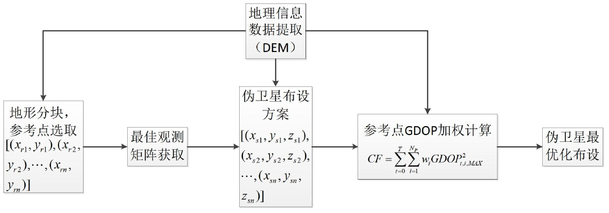
[0011] Such as figure 1 , the present invention adds the optimal observation matrix acquisition operation to the traditional pseudolite deployment technology, and then deploys the pseudolites according to the obtained optimal observation matrix.

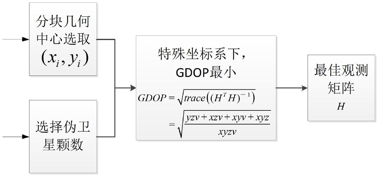
[0012] Such as figure 2 , the present invention obtains the best observation matrix operation. This operation is combined with the actual geographical environment. Firstly, the environment is divided into blocks, and the geometric center point of each block is selected. Use the following operations to obtain the best observation matrix:

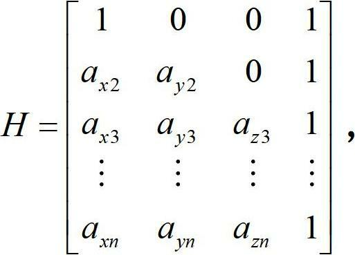
[0013] Pseudolites are numbered s1, s2, s3, ..., sn. Element a in the observation matrix i =(a xi , a yi ,a zi ) is a unit vector pointing to the position of the i-th pseudolite from the linearization point. Take where s1 is on the x-axis, s2 is on the xy plane, and the us...


PUM


Abstract

The invention relates to technology of laying pseudolites. As for traditional technology, the optimal matrix is obtained first. The technology provided by the invention has the characteristic of purposefulness. Due to the adoption of the technology, the pseudolites can be laid onto ideal positions, the laying process is simple, and the stimulation analysis load is small. Moreover, the technology utilizes the relation of the observation matrix and the GDOP (Geometric Dilution of Precision), can effectively improve the positioning precision and is an effective method for optimizing pseudolite laying.

Description

technical field [0001] The present invention relates to a technique for deploying pseudolites, specifically, a technique for deriving an optimum observation matrix by seeking the minimum value of GDOP (Geometrical Dilution of Precision), and deploying pseudolites by utilizing the optimum observation matrix. Background technique [0002] For the general pseudolite deployment technology, the pseudolite is generally placed on the corners to make the volume of the three-dimensional figure formed by the pseudolite the largest, and then the positioning operation and accuracy simulation analysis are performed, and finally the optimal constellation structure is judged, so the layout It is purposeless and the simulation workload is heavy. [0003] Using the best observation matrix to deploy pseudolites is based on the traditional technology of deploying pseudolites. Firstly, the area to be positioned is divided into blocks according to the terrain, and the operation of obtaining the ...

Claims


Application Information

Patent Timeline
IPC IPC(8): G01S19/42G01S19/33
Inventor 张波宋倩李署坚赵斐秦柳
Owner BEIHANG UNIV
Why Eureka
Try Eureka