
Driving method of display unit and driving circuit thereof

A technology of display unit and driving method, which is applied to static indicators, instruments, etc., can solve problems such as afterimages, achieve the effect of improving afterimages and improving display quality

Active Publication Date: 2012-09-19
AU OPTRONICS CORP
View PDF10 Cites 1 Cited by
  • Summary
  • Abstract
  • Description
  • Claims
  • Application Information

AI Technical Summary

Problems solved by technology

Although the electrophoretic display only consumes power at the moment of changing the image, the viscosity of the insulating solvent will limit the moving speed of the charged colored particles, so when the current image is displayed, the previous image may appear Afterimage phenomenon

Method used


Image

  • Driving method of display unit and driving circuit thereof
  • Driving method of display unit and driving circuit thereof
  • Driving method of display unit and driving circuit thereof

Examples


Embodiment Construction

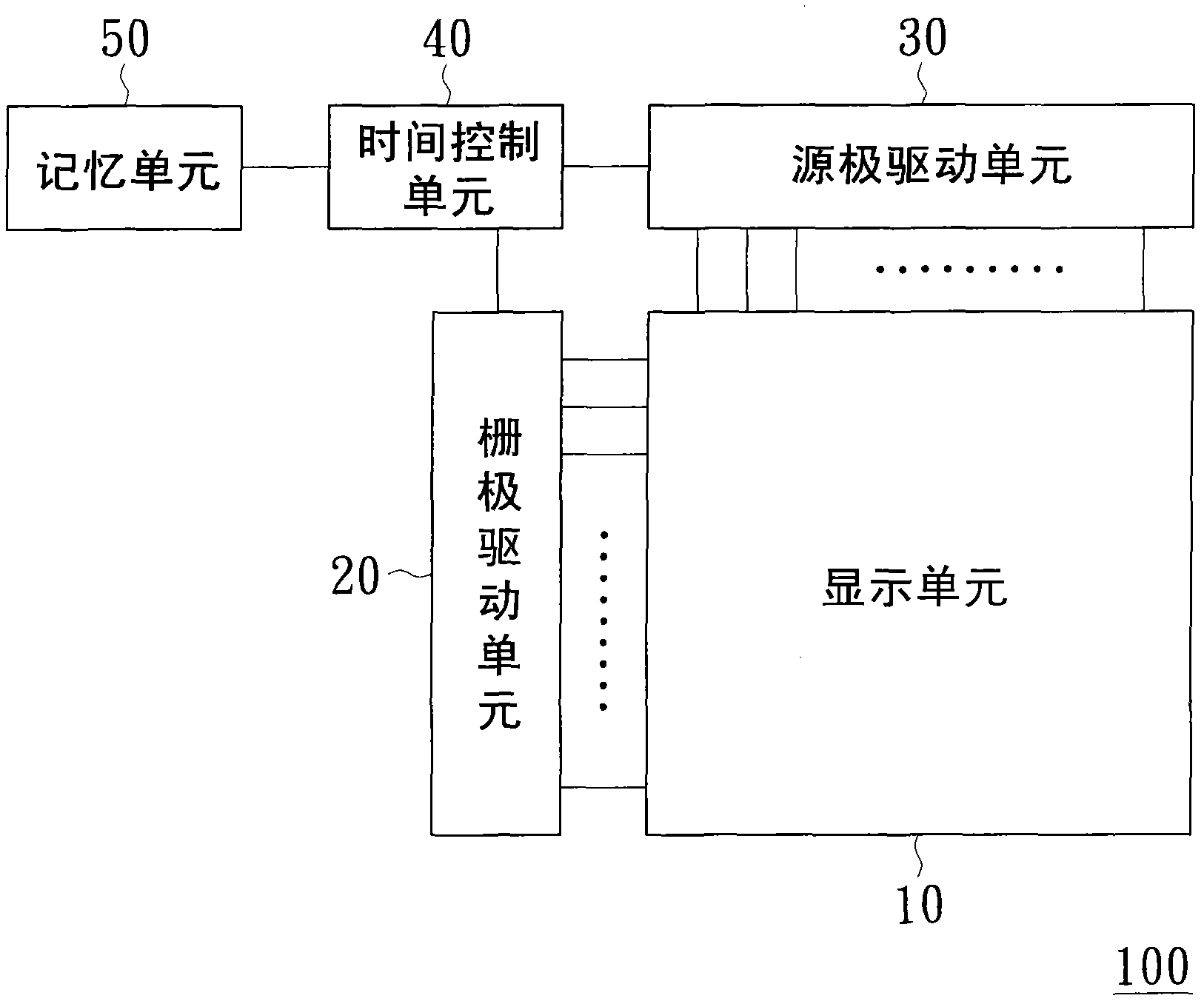
[0039] Please refer to figure 1 , figure 1 It is a circuit block diagram of an embodiment of the present invention. Such as figure 1 As shown, the driving circuit 100 of the display unit 10 of the embodiment of the present invention includes a display unit 10 , a gate driving unit 20 , a source driving unit 30 , a time control unit 40 and a memory unit 50 .

[0040] The display unit 10 includes a plurality of pixel circuits (not shown in the figure), a power supply circuit (not shown in the figure) and / or an optical module (not shown in the figure) and the like. Each pixel circuit may be composed of a thin film transistor (not shown in the figure), a liquid crystal capacitor (not shown in the figure) and a storage capacitor (not shown in the figure). The display unit 10 may eg be a bi-stable display.

[0041] The gate driving unit 20 is electrically coupled to the display unit 10 . The gate driving unit 20 provides a plurality of scan signals to the display unit 10 throug...


PUM


Abstract

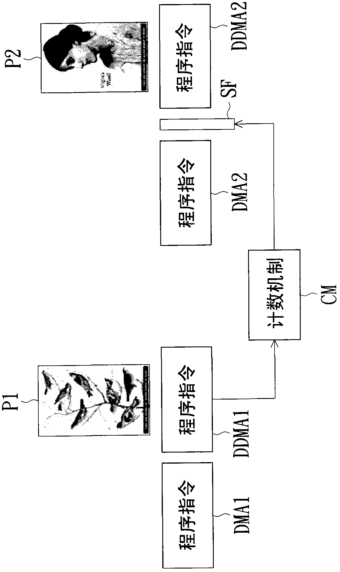
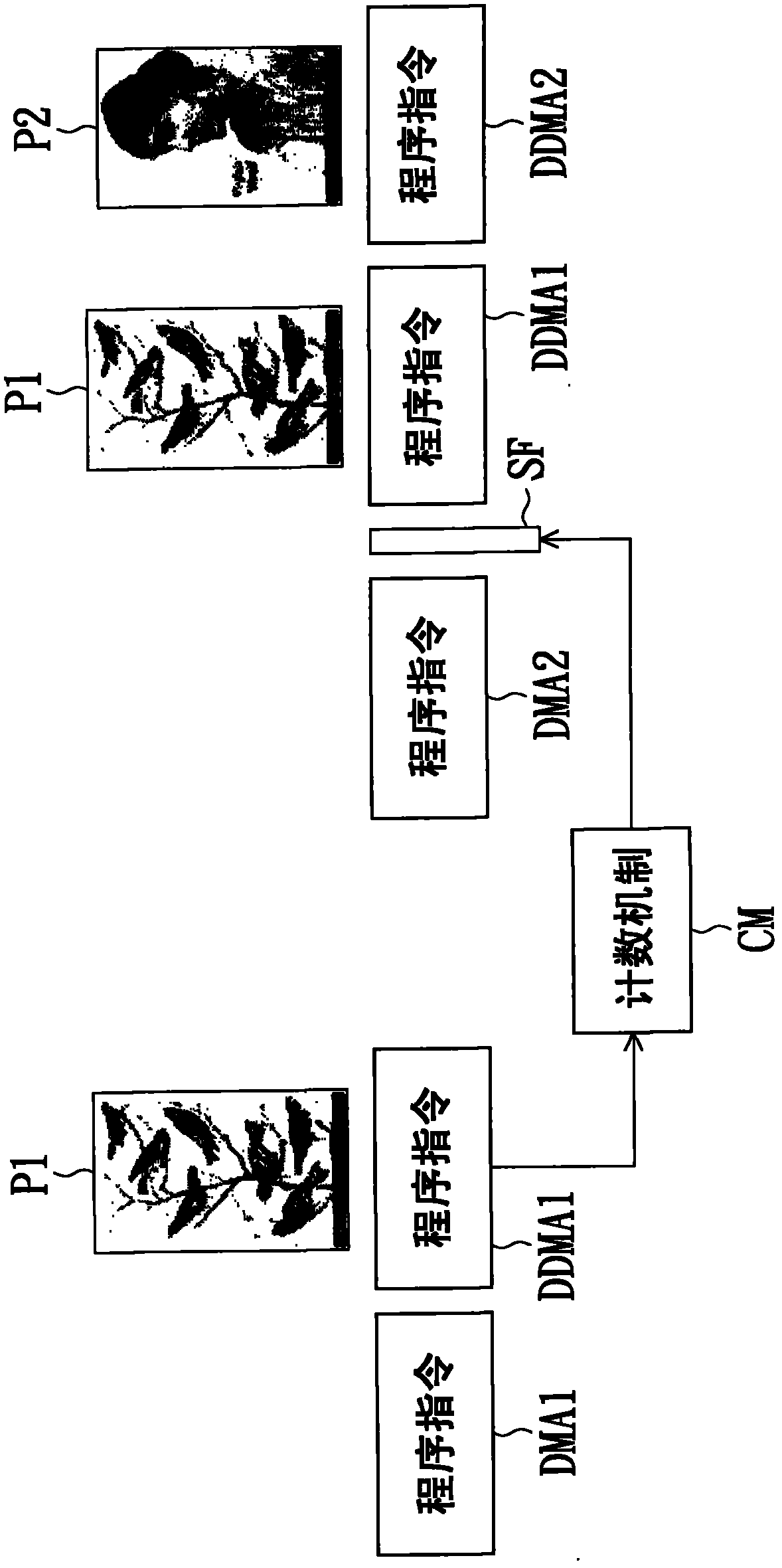
The invention provides a driving method of a display unit and a driving circuit thereof. The driving method comprises the following steps: performing a first display program to display a first picture on the display unit and start a counting mechanism; judging whether the counting value of the counting mechanism is larger than a preset value or not before a second picture display program is determined to perform; firstly performing a special picture display program and then performing the second picture display program when the counting value is determined to be larger than the preset value; performing the second picture display program to display a second picture on the display unit when the counting value is determined to be smaller than or equal to the preset value.

Description

technical field [0001] The present invention relates to a picture driving method, and in particular to a display unit driving method and its driving circuit. Background technique [0002] Among current displays, electrophoretic displays have been gradually favored by consumers in recent years due to advantages such as low power consumption and readability. Although the electrophoretic display only consumes power at the moment of changing the image, the viscosity of the insulating solvent will limit the moving speed of the charged colored particles, so when the current image is displayed, the previous image may appear afterimage phenomenon. Especially when the display time of the previous frame is too long, the image sticking phenomenon is more obvious. Contents of the invention [0003] The invention proposes a driving method of a display unit and a driving circuit thereof, so as to improve the image sticking phenomenon that is easy to occur in current displays (eg, bist...

Claims


Application Information

Patent Timeline
Patent Type & Authority Applications(China)
IPC IPC(8): G09G3/34G09G3/36
CPCG09G2320/048G09G2310/063G09G2320/0257G09G3/3651G09G3/344G09G2300/0473G09G2320/0606G09G3/34G09G3/36G09G2310/0245
Inventor 林峰生赖俊吉郑国兴
Owner AU OPTRONICS CORP
Learn More