Display panel, driving method thereof, and display device

A technology of display panel and driving method, applied in static indicators, instruments, semiconductor devices, etc., can solve the problems of low reset signal, short charging time, adverse effect on display performance, etc.

Active Publication Date: 2021-06-15
WUHAN TIANMA MICRO ELECTRONICS CO LTD
View PDF12 Cites 0 Cited by
  • Summary
  • Abstract
  • Description
  • Claims
  • Application Information

AI Technical Summary

Problems solved by technology

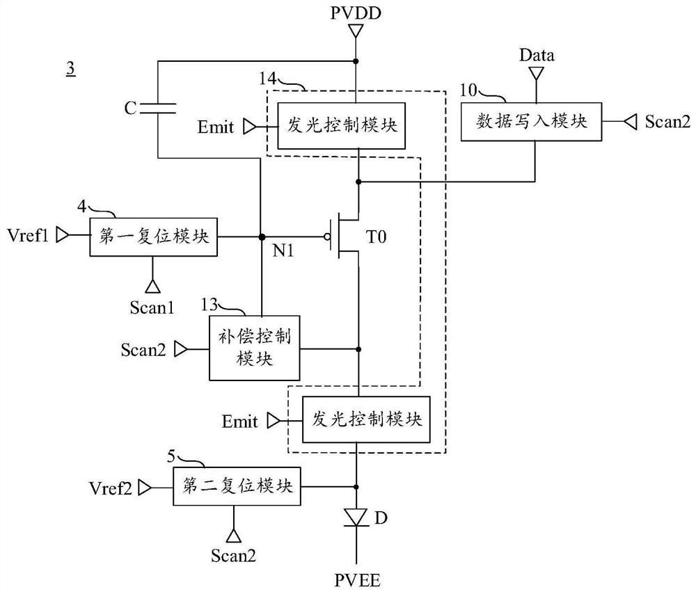
[0003] At present, in order to improve the stealing phenomenon of sub-pixels, it is necessary to use a lower reset signal to reset the anode of the organic light-emitting element. However, since the first reset transistor and the second reset transistor receive the same reset signal, this causes the drive transistor The reset signal received by the gate is also pulled down accordingly, which leads to some adverse effects on display performance
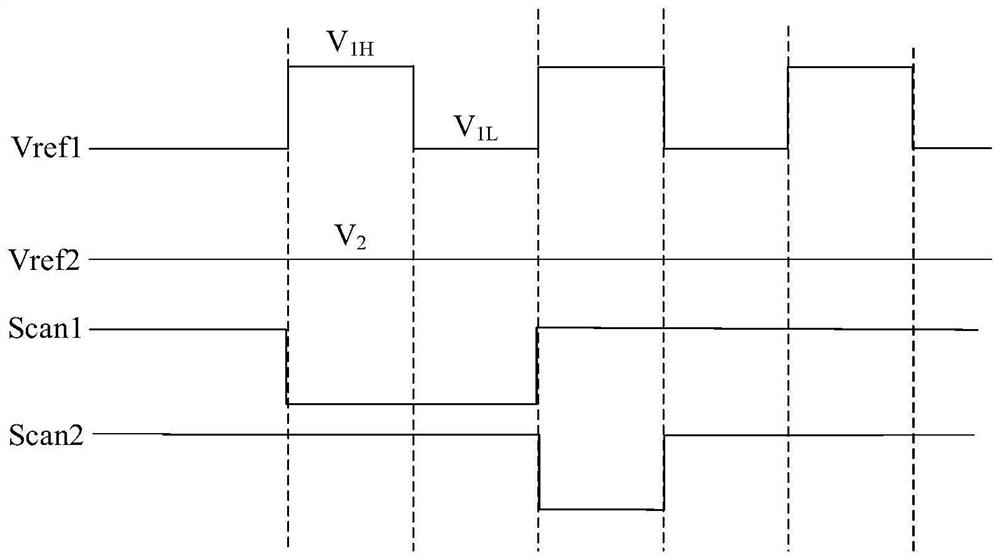
For example, when the reset signal received by the gate of the driving transistor is too low, in the data writing period, the gate of the driving transistor needs to write data voltage on the basis of a very low voltage, plus the pulse of the current scanning signal Shorter width means shorter charging time, which will lead to insufficient charging and make the display brightness deviate

Method used


Image

  • Display panel, driving method thereof, and display device
  • Display panel, driving method thereof, and display device
  • Display panel, driving method thereof, and display device

Examples


Embodiment Construction

[0035] In order to better understand the technical solutions of the present invention, the embodiments of the present invention will be described in detail below in conjunction with the accompanying drawings.

[0036] It should be clear that the described embodiments are only some of the embodiments of the present invention, not all of them. Based on the embodiments of the present invention, all other embodiments obtained by persons of ordinary skill in the art without creative efforts fall within the protection scope of the present invention.

[0037] Terms used in the embodiments of the present invention are only for the purpose of describing specific embodiments, and are not intended to limit the present invention. As used in the embodiments of the present invention and the appended claims, the singular forms "a", "said" and "the" are also intended to include the plural forms unless the context clearly indicates otherwise.

[0038] It should be understood that the term "an...


PUM


Abstract

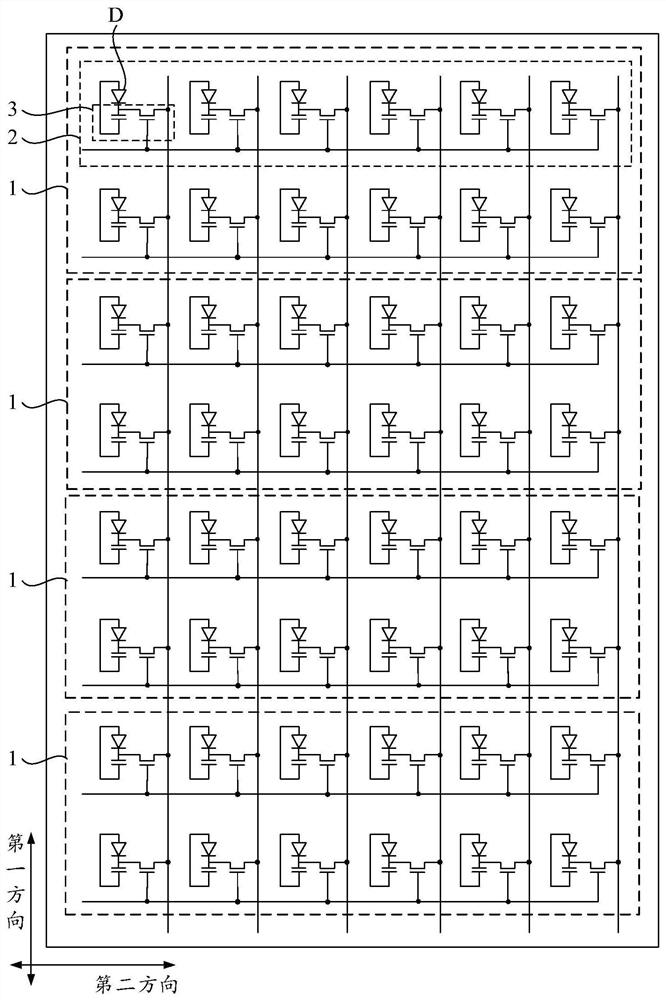
Embodiments of the present invention provide a display panel, a driving method thereof, and a display device, relating to the field of display technology, capable of making charging more sufficient, weakening the difference between the brightness of the first frame and other frames, and effectively improving the afterimage phenomenon. The above display panel includes: n pixel groups, each pixel group includes 2m pixel rows arranged along the first direction, n and m are positive integers greater than or equal to 1; each pixel row includes multiple pixel rows arranged along the second direction A pixel circuit; the pixel circuit includes: a driving transistor; a first reset module, configured to transmit the first reset signal provided by the first reset signal line to the gate of the driving transistor in response to the first scanning signal provided by the first scanning signal line , the first reset signal includes alternating high level and low level; the second reset module is used to respond to the second scan signal provided by the second scan signal line, and transmit the second reset signal provided by the second reset signal line to the organic The anode of the light-emitting element.

Description

【Technical field】 [0001] The present invention relates to the field of display technology, in particular to a display panel, a driving method thereof, and a display device. 【Background technique】 [0002] In the prior art, the pixel circuit includes a drive transistor, a first reset transistor, and a second reset transistor, the first reset transistor and the second reset transistor are electrically connected to the same reset signal line, and the reset signals supplied by the reset signal terminal line are respectively The gate of the driving transistor and the anode of the organic light emitting element are reset. [0003] At present, in order to improve the stealing phenomenon of sub-pixels, it is necessary to use a lower reset signal to reset the anode of the organic light-emitting element. However, since the first reset transistor and the second reset transistor receive the same reset signal, this causes the drive transistor The reset signal received by the grid is als...

Claims


Application Information

Patent Timeline
Patent Type & Authority Patents(China)
IPC IPC(8): G09G3/3208
CPCG09G3/3208G09G2310/0262G09G2300/0819G09G2300/0842G09G2300/0861G09G2310/0251G09G3/3233G09G2320/045G09G3/3241G09G3/3266G09G3/3275G09G2310/0278G09G2310/0286H10K59/131
Inventor 王宝男李欣敦栋梁夏志强
Owner WUHAN TIANMA MICRO ELECTRONICS CO LTD
Why Eureka
Try Eureka