Driving method for liquid crystal sub-pixel

A driving method and sub-pixel technology, applied in instruments, static indicators, etc., can solve the problem of limited image quality improvement.

Active Publication Date: 2009-08-12
AU OPTRONICS CORP
View PDF0 Cites 0 Cited by
  • Summary
  • Abstract
  • Description
  • Claims
  • Application Information

AI Technical Summary

Problems solved by technology

However, regardless of the above-mentioned solutions, th...

Method used


Image

  • Driving method for liquid crystal sub-pixel
  • Driving method for liquid crystal sub-pixel
  • Driving method for liquid crystal sub-pixel

Examples


no. 1 example

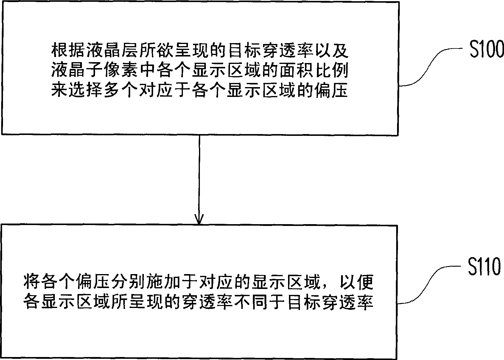
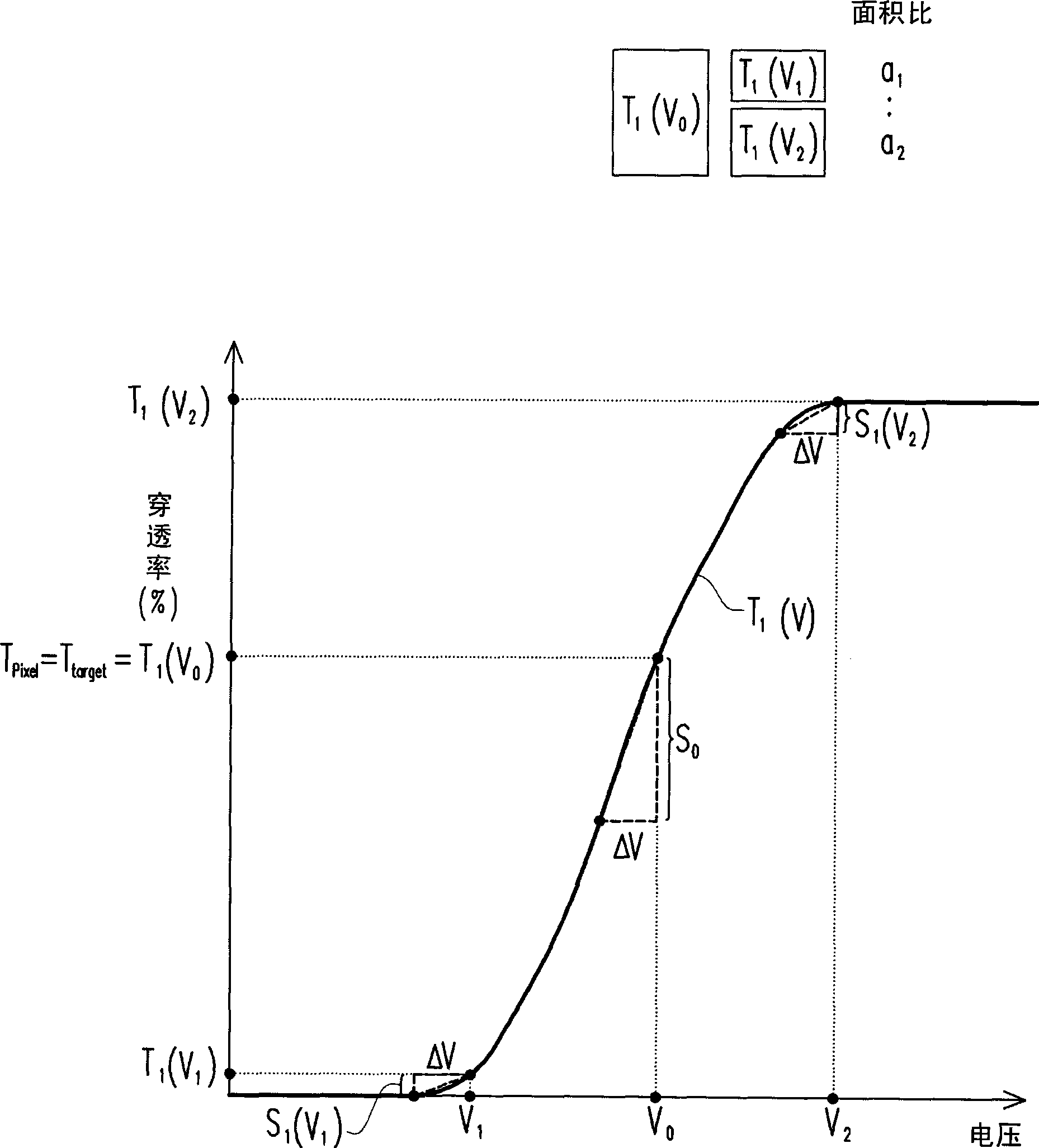
[0037] figure 1 is a flow chart of the driving method according to the first embodiment of the present invention. Please refer to figure 1 , the driving method of this embodiment is suitable for determining a target transmittance T to be presented by a liquid crystal layer in a liquid crystal sub-pixel target (n), wherein the liquid crystal sub-pixel has a plurality of display areas that can be individually controlled, when the bias voltage applied to each display area is the same, and the transmittance presented by the liquid crystal layer is the target transmittance T target (n), and when the bias voltage varies by ΔV, the transmittance of the liquid crystal layer in the liquid crystal sub-pixel varies as S 0 . Here, the bias voltage variation ΔV is caused by, for example, charged impurities or ions in the liquid crystal layer, and the reason thereof has been described in the prior art, so it will not be repeated here.

[0038] The driving method of this embodiment inclu...

no. 2 example

[0057] Please refer to relational expression (1) and relational expression (2) in the first embodiment, when n=2, a 1 ≠a 2 , and the voltage-transmittance curves of the liquid crystal layers in each display area are different, the aforementioned relational expression (1) and relational expression (2) can be simplified as follows:

[0058] T pixel = a 1 × T 1 ( V 1 ) + a 2 × T 2 ( V 2 ) a 1 + ...

no. 3 example

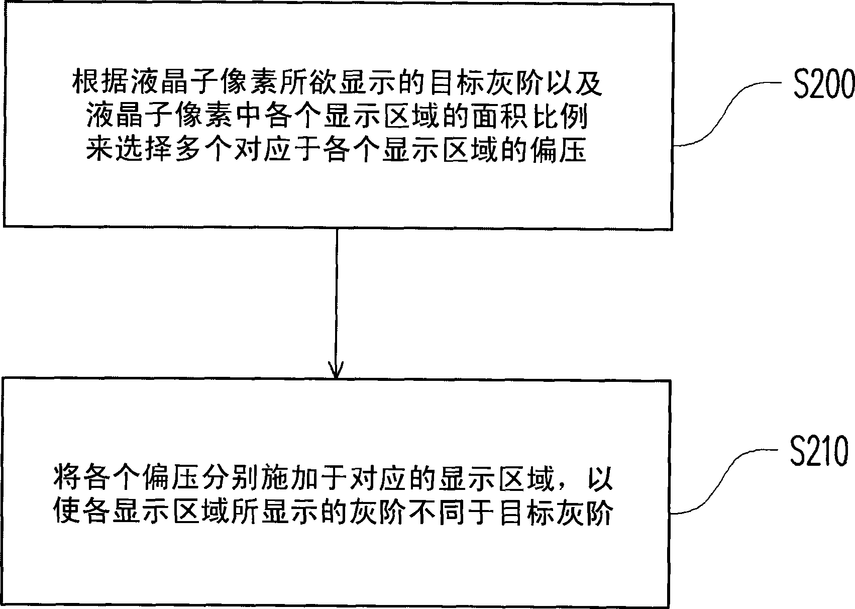
[0066] Since the transmittance of the liquid crystal layer in the liquid crystal pixel has a certain correlation with the grayscale brightness that the liquid crystal pixel can display, this embodiment uses the grayscale brightness and the variation of the grayscale brightness as the basis for selecting the bias voltage applied to each display area. in accordance with.

[0067] image 3 is a flow chart of the driving method according to the third embodiment of the present invention. Please refer to image 3 , the driving method of this embodiment is suitable for making a liquid crystal sub-pixel display a target grayscale brightness L target (n), wherein the liquid crystal sub-pixel has a plurality of display areas that can be individually controlled, when the bias voltage applied to each display area is the same, and the gray-scale brightness displayed by the liquid crystal sub-pixel is the target gray-scale brightness L target (n), and when the bias voltage varies by ΔV, ...


PUM


Abstract

The invention relates to a driving method, which is suitable for driving a liquid crystal sub-pixel which is provided with n display areas. When the bias voltage applied on various display areas is all V0, the penetrating power of a liquid crystal layer in a liquid crystal sub-pixel is Tpixel; and when the bias voltage is subjected to delta V mutation, the penetrating power of the liquid crystal layer in the liquid crystal sub-pixel is mutated into S0. The driving method is to apply the bias voltage Vk on the various display areas, so that the penetrating power of liquid crystal layers in various display areas is Tk(Vk), wherein k is more than or equal to 1 and less than or equal to n, and n is more than or equal to 2; and the area of the various display areas is ak, and the ak and the Tk(Vk) meet a relational expression (1). When the bias voltage applied on the various display areas meets the relational expression (1) and is subjected to delta V mutation, the penetrating power of the liquid crystal layers in the various display areas is mutated into Sk(Vk), and the overall penetrating power of the liquid crystal layers in the liquid crystal sub-pixel is mutated into Spixel; and the Sk(Vk) and the Spixel meet a relational expression (2).

Description

technical field [0001] The present invention relates to a driving method of a liquid crystal sub-pixel, and in particular to a driving method of a liquid crystal sub-pixel capable of improving image sticking. Background technique [0002] Liquid crystal display panels with superior characteristics such as high image quality, good space utilization efficiency, low power consumption, and no radiation have gradually become the mainstream of displays. Generally speaking, there will inevitably be some charged impurities or ions in the liquid crystal layer of the liquid crystal display panel, and after a long time of driving, the distribution of these charged impurities or ions will gradually change, resulting in display Deterioration in quality. In detail, under long-time driving, the impurities or ions in the liquid crystal layer will produce positive and negative separation according to their polarity, and these impurities or ions separated according to the polarity will consu...

Claims


Application Information

Patent Timeline
IPC IPC(8): G09G3/36
Inventor 陈予洁廖干煌刘品妙
Owner AU OPTRONICS CORP
Why Eureka
Try Eureka