
Multichannel synchronous recording method

A synchronous recording and multi-channel technology, applied in the direction of carrier index/addressing/timing/synchronization, image communication, record carrier editing, etc., can solve the problems of difficult selection, missing wonderful shots, missing wonderful moments, etc.

Inactive Publication Date: 2015-06-17
CHINA DIGITAL VIDEO BEIJING
View PDF3 Cites 0 Cited by
  • Summary
  • Abstract
  • Description
  • Claims
  • Application Information

AI Technical Summary

Problems solved by technology

[0003] When recording large-scale TV programs, such as large-scale evening parties and sports events, TV stations usually use multiple cameras for multi-angle shooting. Although there are multiple cameras for shooting, there is only one recording signal. performance, may miss other wonderful shots, resulting in unsatisfactory recorded video signal, leaving all kinds of regrets that cannot be made up
In particular, for complex scenes, interlaced application of multi-camera lenses, and detailed program requirements, it is more difficult to choose when switching output
[0004] In the process of realizing the present invention, the inventor found the following disadvantages in the prior art: when using multi-camera and multi-angle shooting, when switching, usually the director selects one signal to keep through observation and sends it to the video recorder recording, but there are often many wonderful shots at the same moment, and some wonderful moments will be missed at this time, resulting in irreparable regrets
Although late-stage non-linear editing systems are more and more widely used, each non-linear editing system can only upload and edit one video and audio signal at the same time
Unable to meet the requirements of refined editing and rapid production of video programs

Method used


Image

  • Multichannel synchronous recording method

Examples


Embodiment Construction

[0015] The following will clearly and completely describe the technical solutions in the embodiments of the present invention with reference to the accompanying drawings in the embodiments of the present invention. Obviously, the described embodiments are some of the embodiments of the present invention, but not all of them. Based on the embodiments of the present invention, all other embodiments obtained by persons of ordinary skill in the art without creative efforts fall within the protection scope of the present invention.

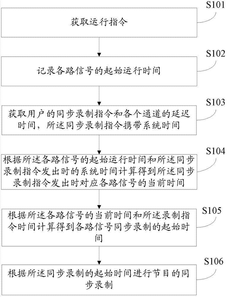
[0016] Embodiment 1 of the present invention discloses a method for multi-channel synchronous recording, such as figure 1 shown, including the following steps:

[0017] Step S101, acquiring an operation instruction, the operation instruction is used to start receiving signals from various channels.

[0018] Step S102, record the initial running time of each signal.

[0019] Step S103, acquiring the user's synchronous recording instruction and the de...


PUM


Abstract

The invention discloses a multichannel synchronous recording method, which comprises the steps as follows: obtaining an operating instruction; recording the initial operation time of each path of signal; obtaining a synchronous recording command of a subscriber, recording the current system time and obtaining the delay time of each channel; calculating to obtain the current time of each path of corresponding signal at the time of sending the synchronous record command according to the initial operation time of each path of signal and the system time when the synchronous record command is sent; calculating to obtain the starting time of synchronous recording of each path of signal according to the current time of each path of signal and the delay time; and carrying out synchronous recording on program according to the starting time of synchronous recording. According to the invention, multichannel synchronous recording is realized by receiving multiplex signals on a single machine, so that a staffer can comprehensively consider the signals from cameras of each angle at the time of post production of the program; and on the premise of meeting the refined editing of the video cassette program, the program production efficiency is greatly improved, the program production quality is improved and the production cost is lowered.

Description

technical field [0001] The invention relates to the technical field of program production, in particular to a multi-channel synchronous recording method. Background technique [0002] The TV programs played by the TV stations enjoyed by the audience generally need to be recorded, produced and broadcast before they can be finally presented to the audience. [0003] When recording large-scale TV programs, such as large-scale evening parties and sports events, TV stations usually use multiple cameras for multi-angle shooting. Although there are multiple cameras for shooting, there is only one recording signal. During the performance, other wonderful shots may be missed, resulting in unsatisfactory recorded video signals, leaving all kinds of regrets that cannot be made up. In particular, it is more difficult to choose when switching outputs for complex scenes, interlaced application of multi-camera lenses, and detailed program requirements. [0004] In the process of realizin...

Claims


Application Information

Patent Timeline
Patent Type & Authority Patents(China)
IPC IPC(8): G11B27/10G11B27/034H04N5/222H04N5/76
Inventor 何宇飞李庆庄朱延武武皓
Owner CHINA DIGITAL VIDEO BEIJING
Learn More