Communication cavity device and elliptic function type high-pass filtering channel thereof

A high-pass filtering and elliptic function technology, applied in waveguide-type devices, circuits, electrical components, etc., can solve problems such as inability to meet requirements, high out-of-band suppression, large standing waves, etc. High, low insertion loss effect

Active Publication Date: 2012-09-19
COMBA TELECOM TECH (GUANGZHOU) CO LTD +1
View PDF10 Cites 9 Cited by
  • Summary
  • Abstract
  • Description
  • Claims
  • Application Information

AI Technical Summary

Problems solved by technology

The combination of the radio and television system and the mobile communication system has its particularity. On the one hand, a high degree of isolation is required between the two systems; The way the filter is implemented cannot meet the requirements. At this time, a high-pass filter is needed to solve the problem
[0003] Traditional high-pass filters tend to use series capacitors, but series capacitors are difficult to implement, so lumped parameters are generally used
However, the high-pass filter implemented by the lumped parameter method has inherent defects such as large loss and large standing wave, which limits its application.
[0004] CN2059532U Patent Announcement discloses a low-loss broadband high-pass filter, which uses a coaxial transmission line to realize a Chebyshev-type high-pass filter. unable to meet demand
[0005] On the other hand, the technical solution disclosed in CN2059532U Patent Announcement has a basically solidified structure, which is inconvenient to flexibly adjust various parameters, and is not helpful for product diversification.

Method used


Image

  • Communication cavity device and elliptic function type high-pass filtering channel thereof
  • Communication cavity device and elliptic function type high-pass filtering channel thereof
  • Communication cavity device and elliptic function type high-pass filtering channel thereof

Examples


Embodiment Construction

[0025] Below in conjunction with accompanying drawing and embodiment the present invention will be further described:

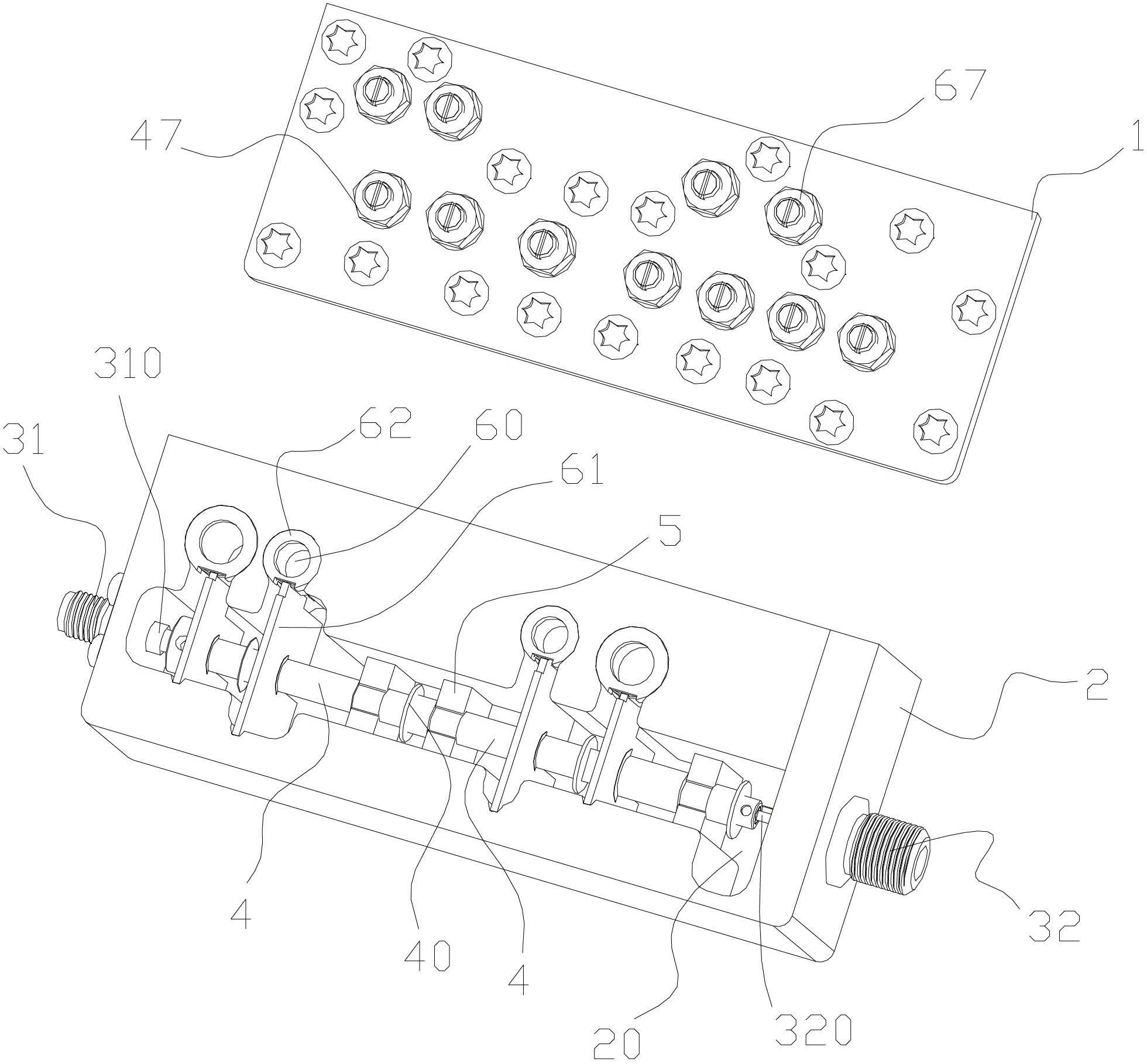
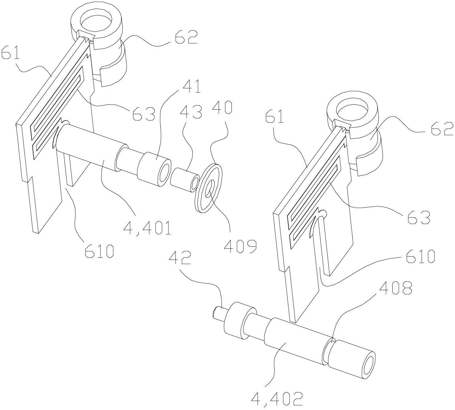
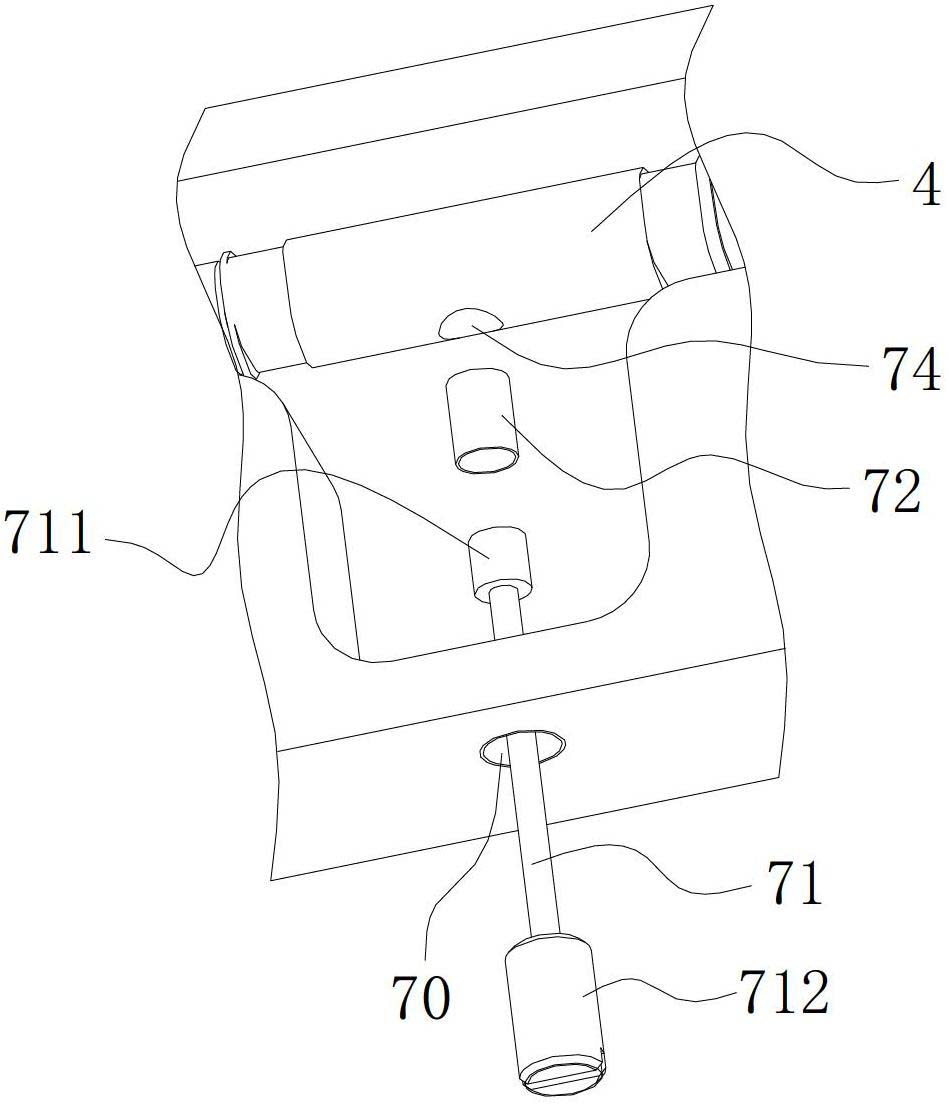
[0026] see figure 1 , in the schematic diagram of the assembly structure of the first embodiment of the elliptic function type high-pass filter channel of the present invention, the high-pass filter channel is designed and formed in a metal cavity 2, mainly including a longitudinal cavity formed in the metal cavity 2 20. Two connection ports 31, 32 located on both sides of the cavity 20 in the longitudinal direction and fixed on the cavity wall of the metal cavity 2, and arranged linearly along the longitudinal direction of the cavity 20 and sequentially capacitively coupled to form A plurality of conductor rods 4 of the capacitor connected in series, the conductor rods 4 located at both ends of the cavity 20 in the longitudinal direction are capacitively coupled with the inner conductors 310, 320 of the two connection ports 31, 32 respectively, so as to real...


PUM


Abstract

The invention discloses an elliptic function type high-pass filtering channel, which comprises a cavity and a cover plate, wherein the cavity is provided with a lengthwise hollow cavity; a plurality of conductor rods which are sequentially and capacitively coupled are arranged along a lengthwise direction linearity of the hollow cavity; the conductor rods at two ends of the lengthwise direction are respectively and capacitively coupled with two connection ports arranged on the cavity; ends for realizing capacitive coupling are arranged between the adjacent conductor rods and/or the conductor rods and one connection ports; a sleeve is formed by a first end and a core column is formed by a second end; a core column of the second end is placed in the sleeve of the first end to form an open circuit coaxial cable, so as to realize the capacitive coupling; a coupling element is further arranged between the first end and the second end; the coupling element is a sheet-shaped medium piece which has two sides covered by conductive layers and is used for the core column to pass through; the two conductive layers are respectively connected with the first end and the second end. The high-pass filtering channel has the characteristics of simple structure, convenience for tuning, wide pass band, small insertion loss, high out-of-band suppression degree and the like.

Description

【Technical field】 [0001] The invention relates to a communication cavity device for performing high-pass filtering on communication signals, in particular to an elliptic function type high-pass filtering path. 【Background technique】 [0002] With the development of the integration of three networks, various demands have been generated by the combination of the radio frequency band and the mobile communication band. The combination of the radio and television system and the mobile communication system has its particularity. On the one hand, a high degree of isolation is required between the two systems; The way the filter is implemented cannot meet the requirements. At this time, a high-pass filter is needed to solve the problem. [0003] Traditional high-pass filters tend to use series capacitors, but series capacitors are difficult to implement, so lumped parameters are generally used. However, the high-pass filter implemented by the lumped parameter method has inherent d...

Claims


Application Information

Patent Timeline
Patent Type & Authority Applications(China)
IPC IPC(8): H01P1/207H01P1/208H01P1/20H01P1/213
Inventor 黄建平邸英杰黄友胜张志浩
Owner COMBA TELECOM TECH (GUANGZHOU) CO LTD
Why Eureka
Try Eureka