Dielectric waveguide resonator and its port coupling adjustment method and filter

A technology of dielectric waveguide and adjustment method, which is applied in the direction of resonators, waveguide devices, circuits, etc., and can solve problems such as difficult processing and metallization, unsuitable for mass production, and limited external dimensions.

Active Publication Date: 2021-03-12
COMBA TELECOM TECH (GUANGZHOU) CO LTD
View PDF9 Cites 0 Cited by
  • Summary
  • Abstract
  • Description
  • Claims
  • Application Information

AI Technical Summary

Problems solved by technology

If the port is located on the bottom of the dielectric waveguide resonator, strong coupling can be achieved, but the design of the dielectric waveguide filter will be limited by the size, and the design limitations are large; if the port is located on the side of the dielectric waveguide resonator, conventional methods need Strong coupling can only be achieved by setting deep blind holes on the side. In practical applications, processing and metallization are difficult, and it is not suitable for mass production.

Method used


Image

  • Dielectric waveguide resonator and its port coupling adjustment method and filter
  • Dielectric waveguide resonator and its port coupling adjustment method and filter
  • Dielectric waveguide resonator and its port coupling adjustment method and filter

Examples


Embodiment Construction

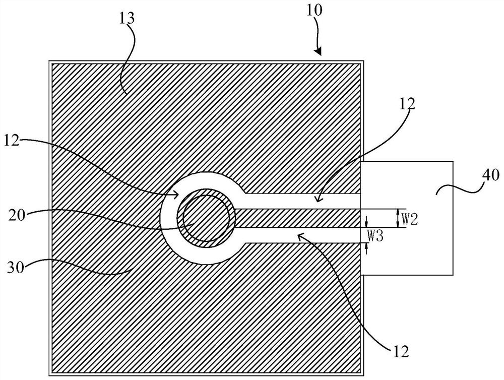
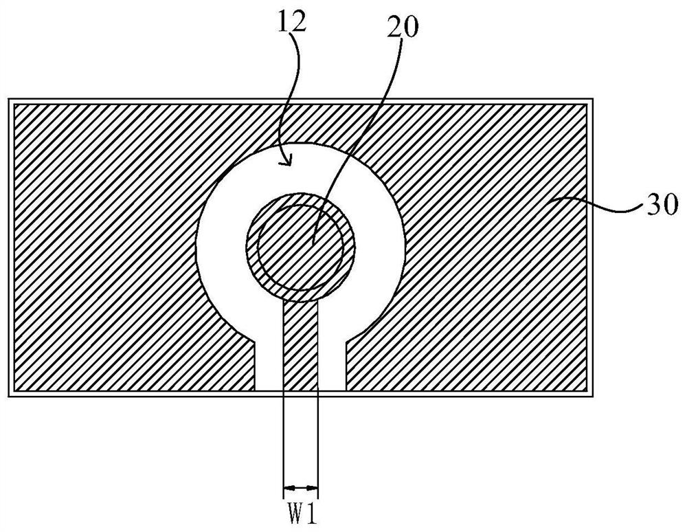
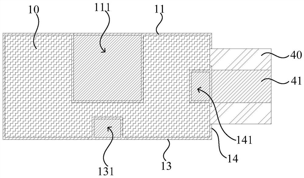
[0033] In order to make the above objects, features and advantages of the present invention more comprehensible, specific implementations of the present invention will be described in detail below in conjunction with the accompanying drawings. In the following description, numerous specific details are set forth in order to provide a thorough understanding of the present invention. However, the present invention can be implemented in many other ways different from those described here, and those skilled in the art can make similar improvements without departing from the connotation of the present invention, so the present invention is not limited by the specific embodiments disclosed below.

[0034] In the description of the present invention, it should be understood that the terms "first" and "second" are used for description purposes only, and cannot be interpreted as indicating or implying relative importance or implicitly indicating the quantity of indicated technical featu...


PUM


Abstract

The invention relates to a dielectric waveguide resonator, a method for adjusting a coupling amount of a port thereof and a filter. The dielectric waveguide resonator comprises a dielectric block; a hollowed-out area for exposing the dielectric block is disposed between a first metal layer and a second metal layer; the hollowed-out area is disposed on the periphery of the first metal layer; the first metal layer includes a first cover layer, a second cover layer and a connection layer; the first cover layer covers a bottom surface of the dielectric block; and the second cover layer covers sidesurfaces of the dielectric block. According to the above-mentioned dielectric waveguide resonator, because the first cover layer covers the bottom surface of the dielectric block, strong coupling ofthe port can be implemented, a condition is provided for widening the bandwidth of the dielectric waveguide resonator, and the above dielectric waveguide resonator can be widely applied to the dielectric waveguide resonator having wider bandwidth; in addition, because the second cover layer is located on the side surface of the dielectric block and is used for connecting a coaxial connector or a signal connector of a PCB (Printed Circuit Board), the design method is less restricted by the external dimensions during design and the mass production can be facilitated.

Description

technical field [0001] The invention relates to the technical field of filters, in particular to a dielectric waveguide resonator, a method for adjusting the coupling amount of ports thereof, and a filter. Background technique [0002] When designing a dielectric waveguide filter, port design is required. The size of the port coupling of the dielectric waveguide filter is related to the bandwidth. The wider the bandwidth, the greater the port coupling requirement. A traditional dielectric waveguide filter is composed of more than two dielectric waveguide resonators. The top surface of the dielectric waveguide resonator is provided with a resonant hole, and the side or bottom surface is provided with ports. If the port is located on the bottom of the dielectric waveguide resonator, strong coupling can be achieved, but the design of the dielectric waveguide filter will be limited by the size, and the design limitations are large; if the port is located on the side of the diele...

Claims


Application Information

Patent Timeline
Patent Type & Authority Patents(China)
IPC IPC(8): H01P7/10H01P11/00H01P1/20
CPCH01P1/2002H01P7/10H01P11/008
Inventor 欧阳洲丁海林显添
Owner COMBA TELECOM TECH (GUANGZHOU) CO LTD
Why Eureka
Try Eureka