Display device

a technology of display device and display screen, which is applied in the field of luminescent crystals, can solve the problems of impossible display of highly saturated colors, and achieve the effect of simple technologies

Active Publication Date: 2019-01-17
AVANTAMA AG
View PDF10 Cites 25 Cited by
  • Summary
  • Abstract
  • Description
  • Claims
  • Application Information

AI Technical Summary

Benefits of technology

[0053]For the fabrication of films of such color conversion layers, materials with a high absorption rate are advantageous. In particular, a high absorption rate allows the fabrication of thinner films, which is e.g. important for the production of display devices. In addition, thinner films require less matrix material and therefore the costs for their fabrication are reduced.
[0054]A concurrent high quantum yield, RoHS compliance, low material usage, a stable peak position and narrow FWHM in the emitted spectrum, a tunable emission spectrum and a high stability represents a major achievement of the present invention over the art. Conventionally, CdSe or InP materials were suggested for LCs. However, while the first provides a sufficient quantum yield, RoHS compliance is challenging and often relies on regulatory exemptions. The latter on the other hand is RoHS compliant but shows inferior optical qualities (quantum yield <60%; FWHM >40 nm). In contrast, the conversion layer portion of the present invention provides both, a good quantum yield, low peak FWHM and RoHS conformity. This is achieved by selecting appropriate materials for LCs, applying appropriate LC concentrations and film thicknesses and at the same time arranging the different LCs in different films, as a result separating the LCs from each other to avoid ion exchange reactions.
[0055]Compared to conventionally used color filters, which tune the color only by absorbing certain wavelengths from the white spectrum the properties of the present embodiments of the invention are superior. While in conventional color filters most of the incident light energy is lost to absorption, in the case of the present invention, depending on the quantum yield of the used materials, more than 90% of the incoming light can be converted to the desired color. This leads to devices with much better energy efficiency.
[0061]In another embodiment, one or more barrier layers may be provided, preferably each barrier layer having a water vapor transmission rate of less than 0.2 (g*mm) / (m̂2*day) at a temperature of 20-50° C. / 90% relative humidity and atmospheric pressure. In any of the above and below embodiments, the device may include a barrier layer on top of an otherwise exposed surface of the color conversion layer. Such barrier layer may in particular have a low water vapour transmission rate in order to avoid a degradation of the LCs in the film / s in response to being exposed to water. The barrier layer may in one embodiment be permeable for O2, or, in a different embodiment, may also be impermeable for oxygen. Preferably, the barrier layer is transmissive for light, and preferably, such barrier layer may be present in the form of a single layer or in the form of multilayers. The barrier layer preferably comprises organic polymers and / or inorganic materials. Suitable organic polymers may be selected from the group consisting of polyvinylidene chlorides (PVdC), cyclic olefin copolymer (COC), high-density polyethylene (HDPE); suitable inorganic materials may be selected from the group consisting of metal oxides, SiOx, SixNy. Most preferably, a polymer barrier layer comprises materials selected from the group of PVdC and COC.
[0082]A “suspension” as used above in the aspect related to manufacturing is known and relates to a heterogeneous fluid of an internal phase (i.p.) that is a solid and an external phase (e.p.) that is a liquid. The external phase comprises one or more dispersants / surfactants, optionally one or more solvents and optionally one or more pre-polymers or dissolved polymers. Accordingly, each type of luminescent crystal (first, second) is added to the dedicated portion of suspension. Further processing includes the application of one or each portion of suspension to the desired area on the substrate. This step is also referred to as solution processing which denotes the application of a coating or thin film to a substrate by the use of a solution-based (=liquid) starting material. This is considered a significant advantage, as it enables manufacturing of all films by simple technologies applicable to large areas and continuous processing.

Problems solved by technology

The color gamut of such displays is limited to the color spectrum emitted by the respective light source, which light source is typically not centred to the primary red, blue, and green wavelengths, and thus renders the displaying of highly saturated colors impossible.

Method used


Image

  • Display device
  • Display device

Examples


example 1

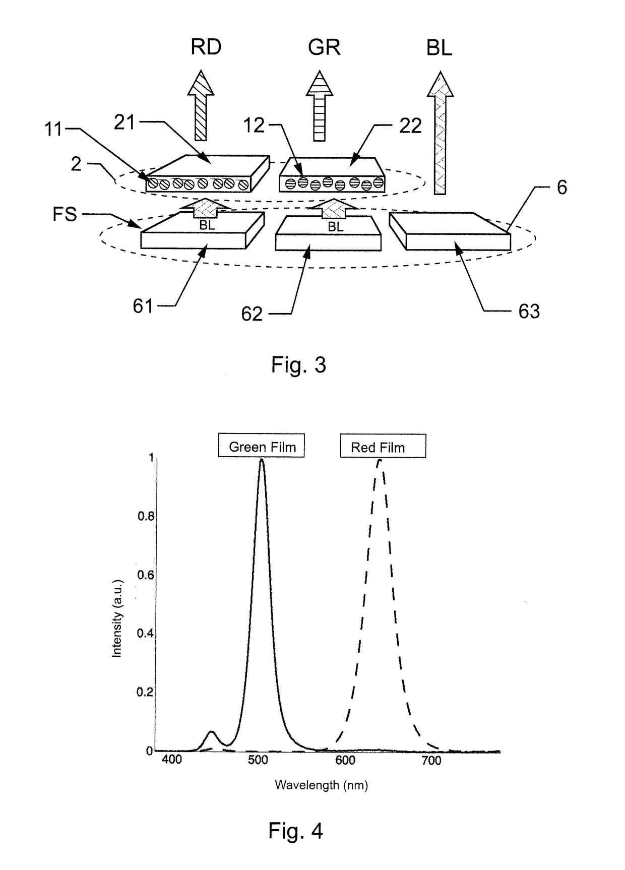
[0105]Luminescent crystals with green emission (LCs) were synthesized according to literature procedure presented by Protesescu et al. (Nano Lett., 2015, 15, 3692-3696). The LCs concentration was defined as 0.54% by heating up the dispersion to 450° C., which led to evaporation of the solvent and burning away the ligands. The dispersion was optically characterized with a Quantaurus C11347-11 Total Quantum Yield device (equipped with an integration sphere). The LCs dispersion, excited at 450 nm had a photoluminescence peak centered at 500 nm with a FWHM of 23 nm and a photoluminescence quantum yield of 89%.

[0106]11.75 wt % of this formulation was mixed with 87.25 wt % of 30 wt % PMMA (Plexiglas 7N) solution in toluene and 1 wt % TiO2 scatter particles (Kronos 2800) and directly poured onto a glass substrate preheated to 60° C. The excess of the mixture was removed with a doctor blade, and after 4 h 60° C. drying resulting in an approximately 400 μm thick film. Upon excitation with 45...

example 2

[0108]Red emitting LCs were synthesized according to literature procedure presented by Protesescu et al. (Nano Lett., 2015, 15, 3692-3696). The LCs concentration was defined as 0.06% by heating up the dispersion to 450° C., which led to evaporation of the solvent and burning away the ligands. The dispersion was optically characterized with a Quantaurus C11347-11 Total Quantum Yield device (equipped with an integration sphere). The LCs dispersion, excited at 450 nm) had a photoluminescence peak centered at 638 nm with a FWHM of 33 nm and a photoluminescence quantum yield of 72%.

[0109]16.875 wt % of this formulation was mixed with 80.125 wt % of 30 wt % PMMA (Plexiglas 7N) solution in toluene and 3 wt % TiO2 scatter particles (Kronos 2800) and directly poured onto a glass substrate preheated to 60° C. The excess of the mixture was removed with a doctor blade, and after 4 h 60° C. drying resulting in an approximately 400 μm thick film. Upon excitation with 450 nm light the film exhibit...


PUM

PropertyMeasurementUnit
sizeaaaaaaaaaa
sizeaaaaaaaaaa
thicknessaaaaaaaaaa

Abstract

A display device includes a light emitter comprising a set of light emitter portions, wherein at least one light emitter portion of the set is configured to emit light with an excitation wavelength, and a color conversion layer including a set of conversion layer portions. At least one conversion layer portion of the set comprises a film comprising a solid polymer composition that includes luminescent crystals of perovskite structure, which are selected from compounds of formula (I): M1aM2bXc (I), wherein M1 represents Cs, M2 represents Pb, and X independently represents anions selected from the group consisting of Cl, Br, I, cyanide, and thiocyanate. The luminescent crystals are of size between 3 nm and 3000 nm, and emit light of a wavelength in response to excitation by the light emitted by at least one corresponding light emitter portion of the set, wherein the excitation wavelength is shorter than the wavelength.

Description

TECHNICAL FIELD[0001]The present invention relates to the field of luminescent crystals (LCs). The invention provides a display device.BACKGROUND ART[0002]Displays are an integral part of our world and are implemented in different sizes into a broad range of electronic devices. In particular color displays are very popular giving rise to various technologies for maximizing their color gamut, i.e. the broad spectrum of colors that can be displayed.[0003]For displaying a broad range of colors, most of the common display technologies, such as the liquid crystal display (LCD) technology, relay on the integration of color filters for filtering the red, green and blue light of the respective light source. The desired color hue is therefore achieved by controlling the intensity of the red, green and blue light.[0004]The color gamut of such displays is limited to the color spectrum emitted by the respective light source, which light source is typically not centred to the primary red, blue, ...

Claims


Application Information

Patent Timeline
Patent Type & Authority Applications(United States)
IPC IPC(8): G02F1/1335H01L27/32H01L33/50
CPCG02F1/133514G02F1/1336G09F9/30C09K11/025C09K11/665G02F1/133617H10K59/38H10K2102/331C09K11/02C09K11/66H01L33/502
Inventor LUCHINGER, NORMANWEBER, INESLOHER, STEFANOSZAJCA, MAREKHARTMEIER, BENJAMIN
Owner AVANTAMA AG
Why Eureka
Try Eureka