Quick joint for high-tension cables

A high-voltage wire, fast technology, applied in the direction of connection, conductive connection, electrical component connection, etc., can solve the problems of low safety, material waste, easy disconnection of joint parts, etc., to improve the wiring speed, reduce costs, and save time. Effect

Inactive Publication Date: 2012-09-19
BAOTOU STEEL GRP BARUN MINING CO LTD
View PDF5 Cites 2 Cited by
  • Summary
  • Abstract
  • Description
  • Claims
  • Application Information

AI Technical Summary

Problems solved by technology

At present, people generally connect the joints of two high-voltage wires side by side, and after winding them side by side with a single-strand aluminum wire, fasten the wound wires with pliers, so

Method used


Image

  • Quick joint for high-tension cables
  • Quick joint for high-tension cables
  • Quick joint for high-tension cables

Examples


Embodiment 1

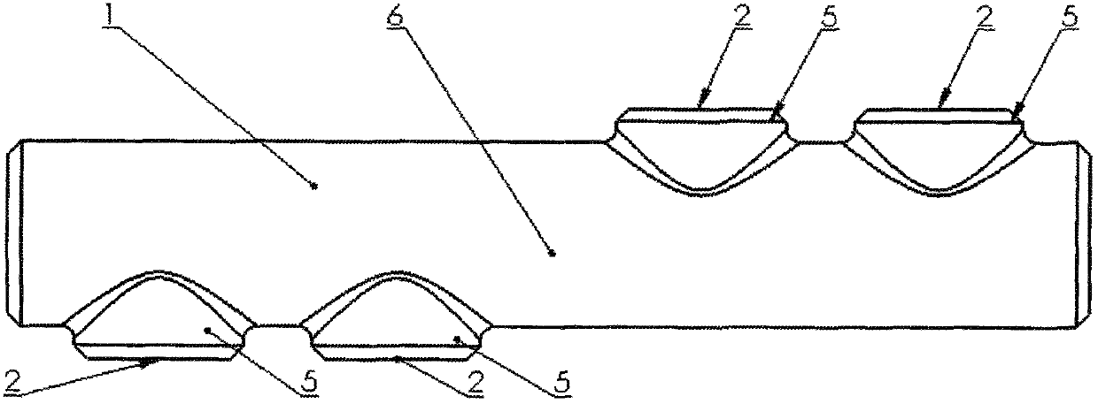
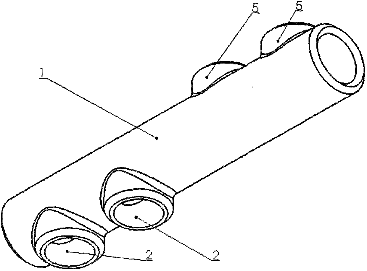
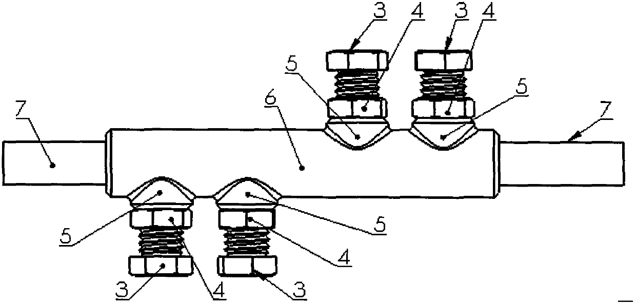
[0030] Both ends of the threading pipe 1 of the present invention are respectively provided with at least one threaded hole 2, the threaded hole 2 is provided with a screw 3, the threaded rod 3 is fixed by a nut 4, and the middle part of the threading pipe is provided with a baffle.

[0031] Installation process

[0032] The present invention only needs to insert the ends of two high-voltage wires 7 to be connected into the left and right threading pipes 1 respectively, so that the ends of the two high-voltage wires 7 are in contact with the baffles 6 in the threading pipe 1 respectively. Then use two screw rods 3 at one end of the threading pipe to rotate and compact the high-voltage line 7 downwards, and at the same time use the nut 4 on the screw rod 3 to self-lock the screw rod 3 to prevent the screw rod 3 from loosening due to swinging. Carry out the same steps at the other end to complete the connection of the high voltage line 7.

Embodiment 2

[0034] At least one boss 5 is provided at both ends of the threading pipe 1, and the middle part of the boss 5 is provided with a threaded hole. The threaded hole is connected with the threading pipe. The threaded hole is provided with a screw, which is fixed by a nut. 6.

[0035] Installation process

[0036] The present invention only needs to insert the ends of two high-voltage wires 7 to be connected into the left and right threading pipes 1 respectively, so that the ends of the two high-voltage wires 7 are in contact with the bottoms of the threading pipes 1 respectively. Then use two screw rods 3 at one end of the threading pipe 1 that are matched with the threaded holes 2 of the boss 5 to rotate downward to compact the high-voltage line 7, and at the same time use the nut 4 on the screw rod 3 to cooperate with the threaded holes 2 of the boss 5 to automatically carry out the screw rod 3 The lock prevents the loosening of the screw rod 3 due to swinging. Carry out the ...

Embodiment 3

[0038] Both ends of the threading pipe 1 of the present invention are respectively provided with at least one threaded hole 2, the threaded hole 2 is provided with a screw 3, the screw 3 is fixed by a nut 4, the threading pipe is placed at both ends of the high-voltage line 7, and the threading pipe and the high-voltage line 7 are crimped and casted .

[0039] Installation process

[0040] The present invention only needs to insert the ends of two high-voltage wires 7 to be connected into the left and right threading pipes 1 respectively, so that the ends of the two high-voltage wires 7 are in contact with the bottoms of the threading pipes 1 respectively. Then use two screw rods 3 at one end of the threading pipe 7 to rotate downwards and compact the high-voltage line 7, and simultaneously use the nut 4 on the screw rod 3 to self-lock the screw rod 3 to prevent the screw rod 3 from loosening due to swinging. Carry out the same steps at the other end to complete the connectio...


PUM


Abstract

The invention relates to a quick joint for high-tension cables and belongs to a basic electric former piece. Each one of two ends of a wire passing pipe provided by the invention is at least provided with a thread hole; a screw rod is arranged on the thread hole; and the screw rod is fixed through a nut. By utilizing the quick joint for the high-tension cables provided by the invention, the time is saved, materials are saved, and the efficiency is improved, so that the cost is reduced, and the high-tension cables with different lengths can be sufficiently and reasonably used. The quick joint for the high-tension cables provided by the invention is simple and easy to know and simple and clear in operation. The screw rod is automatically locked by using a self-locking nut, so as to prevent from the release of the screw rod, caused by swinging. The operation time is greatly reduced, and the stringing speed is improved by using the lever principle, so that various electric devices are ensured to be efficiently operated. Meanwhile, the reasonable length is achieved by rapidly dismounting surplus wires of the quick joint, so that no material waste is caused, and the cost is reduced. Therefore, the purposes of reducing the cost and improving the efficiency can be achieved. The flexible quick joint provided by the invention is convenient to store, and is convenient in mechanical operation. The rapid quick joint has the advantages of low manufacturing cost and convenience in machining..

Description

technical field [0001] The invention relates to a quick connector for a high-voltage line, which belongs to basic electrical and gas parts. Background technique [0002] At present, the stope equipment is changing positions all the time, so the stope needs to continuously set up wires and move the position of the column switch, which requires continuous erection of high-voltage utility poles. The unequal distance between utility poles makes it difficult to determine the length of high-voltage lines. Longer high-voltage lines must be cut to a reasonable length, and short high-voltage lines must be bound to achieve a reasonable length. At present, people generally connect the joints of two high-voltage wires side by side, and after winding them side by side with a single-strand aluminum wire, fasten the wound wires with pliers, so that the two wires to be connected are compacted to achieve The purpose of the connection, this connection method is easy to cause the joints to be...

Claims


Application Information

Patent Timeline
IPC IPC(8): H01R11/00H01R11/09H01R4/36
Inventor 黄大江胡艳英周文刘占全李称心邵玉全王珍涛王杰董占京崔凤郭丽东齐静
Owner BAOTOU STEEL GRP BARUN MINING CO LTD
Why Eureka
Try Eureka