Supercharge Your Innovation With Domain-Expert AI Agents!

Lamp End of Life Detection Circuit

A circuit, driver circuit technology, applied in the field of lighting, can solve problems such as tail cap and gripper overshoot, lamp breakage, overheating, etc.

Inactive Publication Date: 2015-12-16
OSRAM SYLVANIA INC
View PDF5 Cites 0 Cited by
  • Summary
  • Abstract
  • Description
  • Claims
  • Application Information

AI Technical Summary

Problems solved by technology

However, lamps with relatively small diameters (approximately 1.25 inches), such as T5 lamps, are particularly likely to react adversely toward the end of their life
[0005] For example, during its end-of-life (EOL) phase, the tail cap of a T5 lamp can overheat due to the consumption of the exhaust mixture in the filament and due to the small gap between the cathode and the lamp wall
When this occurs, the lamp back cap and holder may exceed design temperature limits and adversely affect lamp system reliability
For example, these conditions may cause the lamp to break

Method used


Image

  • Lamp End of Life Detection Circuit
  • Lamp End of Life Detection Circuit
  • Lamp End of Life Detection Circuit

Examples


Embodiment Construction

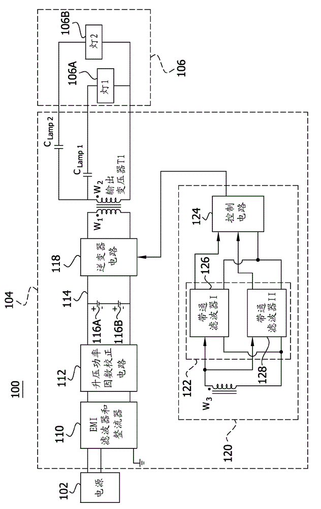
[0023] figure 1 Illustrated is a lamp system 100 including an input power source 102 such as, but not limited to, an alternating current (AC) power source, an electronic ballast 104 and a lamp 106 . While lamp 106 is on figure 1 is shown as two lamps 106A and 106B, but lamp 106 may be a single lamp or multiple lamps connected together in parallel. In some embodiments, lamp 106 is a fluorescent lamp, such as but not limited to a T5 or T8 fluorescent lamp. However, the lamp system 100 may be used to energize other types of lamps without departing from the scope of the present invention.

[0024]Electronic ballast 104 includes one or more input terminals adapted to be connected to input power source 102 and a ground terminal connectable to ground potential. In some embodiments, the input power source 102 includes a first voltage source and a second voltage source. The electronic ballast 104 is operatively connected to said first or second voltage source. Accordingly, electro...


PUM


Abstract

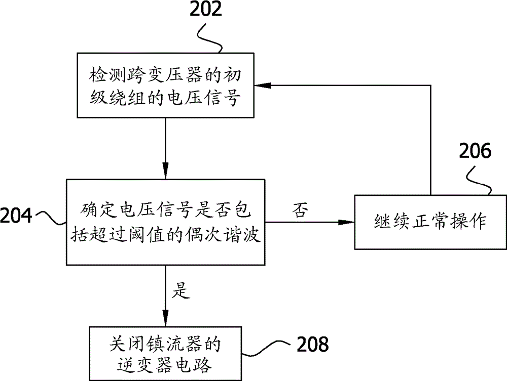
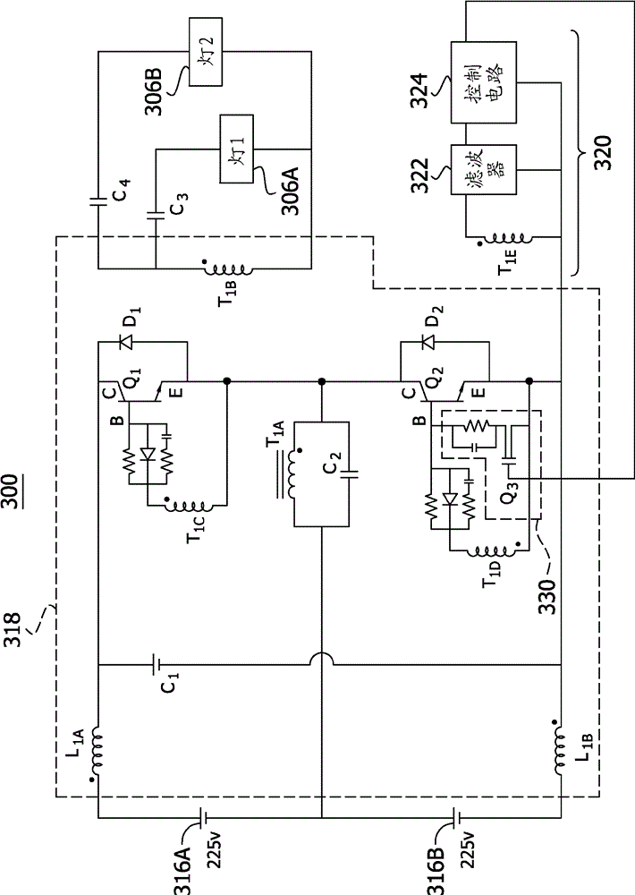
A lamp driver circuit is provided for selectively energizing one or more lamps. The inverter circuit has a transformer with primary and secondary windings for supplying voltage to the lamp. A filter is connected to the primary winding to receive a primary winding signal representing the voltage across the primary winding. The primary winding signal has a frequency spectrum and the filter detects certain characteristics of this frequency spectrum that are indicative of an end-of-life (EOL) condition for one or more lamps. A control circuit is connected to the inverter circuit and the filter. The control circuit is configured to interrupt energization of one or more lamps through the inverter circuit when the filter detects the particular characteristic of the frequency spectrum of the primary winding signal.

Description

[0001] Cross References to Related Applications [0002] This application claims priority to US Provisional Patent Application No. 61 / 293037, entitled "Lamp End of Life (EOL) Detect Circuit for Current Fed Electronic Ballast," filed January 7, 2010, the entire contents of which are hereby incorporated by reference. technical field [0003] This invention relates to lighting, and more particularly to electronic ballasts for lamps. Background technique [0004] Typically, the ballast provides power to the lamp and regulates the current and / or power provided to the lamp. Lamps such as fluorescent lamps use a ballast to provide the lamp with the proper starting voltage and to limit the operating current once the lamp is ignited. One type of fluorescent lamp in common use is the T5 lamp because of the compact size and high lumen efficacy provided by the T5 lamp and corresponding ballast. However, lamps with relatively small diameters (approximately 1.25 inches), such as T5 lamp...

Claims


Application Information

Patent Timeline
Patent Type & Authority Patents(China)
IPC IPC(8): F21S2/00H05B41/298H05B41/46
CPCH05B41/2855H05B41/298H05B41/46
Inventor N.库马S.贝克雷C.布罗伊尔
Owner OSRAM SYLVANIA INC
Features
  • R&D
  • Intellectual Property
  • Life Sciences
  • Materials
  • Tech Scout
  • Unparalleled Data Quality
  • Higher Quality Content
  • 60% Fewer Hallucinations
Learn More