Sliding belt cooling machine

A cooling machine and conveyor belt technology, applied in the field of conveyor belt coolers, can solve problems such as easy blockage of the chute of the conveyor belt cooler

Inactive Publication Date: 2015-01-28
高原晨曦
View PDF4 Cites 0 Cited by
  • Summary
  • Abstract
  • Description
  • Claims
  • Application Information

AI Technical Summary

Problems solved by technology

[0004] In order to solve the defect in the prior art that large pieces of material randomly appearing easily block the chute of the belt cooler, the present invention provides a belt cooler, which is equipped with a large material detection device and a large material handling device. When the bulk material detection device detects bulk material, the bulk material processing device will crush the detected bulk material to eliminate the hidden danger of bulk material blocking the chute and ensure the smooth operation of the material inside the chute

Method used


Image

  • Sliding belt cooling machine
  • Sliding belt cooling machine
  • Sliding belt cooling machine

Examples


Embodiment 1

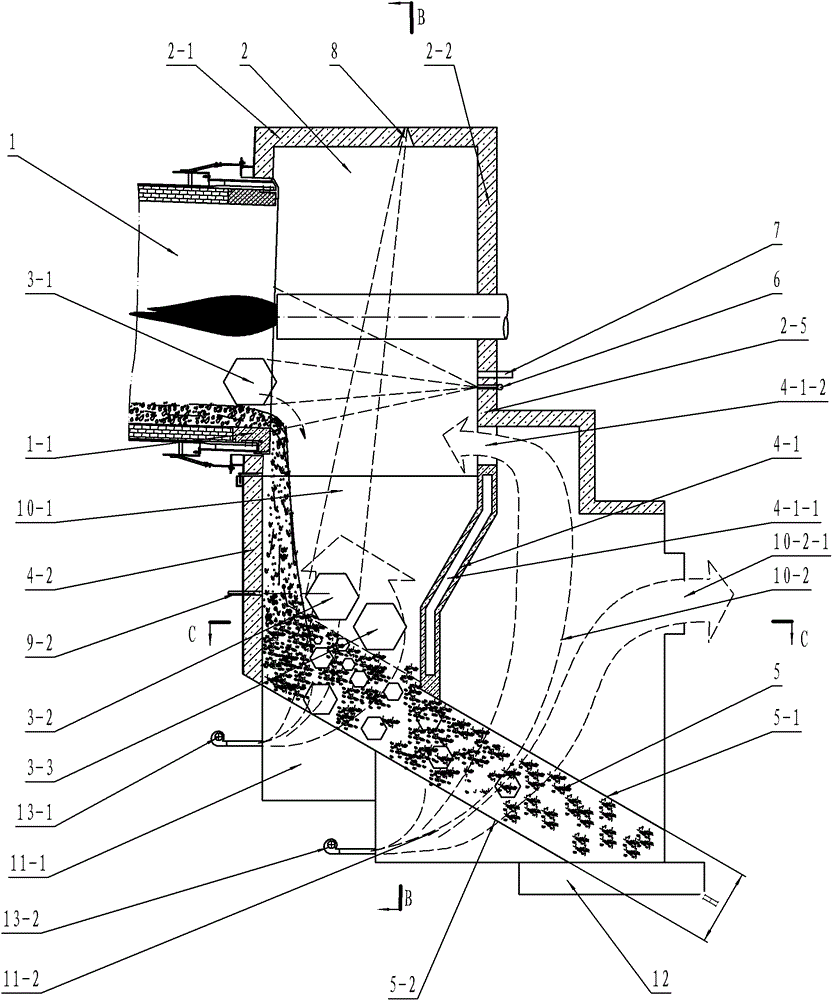
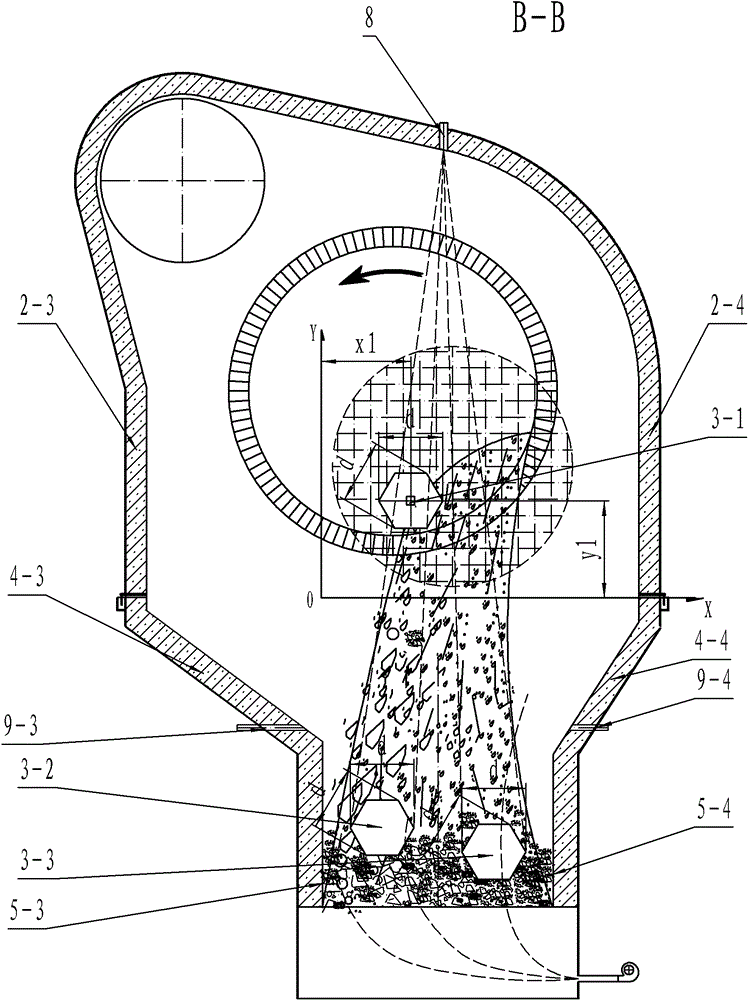
[0058] see figure 1 with figure 2 , Is a schematic diagram of the front structure and a schematic diagram of the B-B direction structure of the belt cooling machine of the present invention. The material fired from the rotary kiln 1 is discharged into the chute 5 through the drainage wall of the drainage wall. The material inside the chute 5 slides from the inlet end of the chute to the outlet end of the chute by its own weight and is discharged through the unloader 12. When the material is falling, the cooling gas provided by the fan 13-1 and the fan 13-2 cools down the material in the chute to achieve the purpose of cooling the material. It can be seen that the entire belt cooler is an unpowered conveying system, and the conveying of materials completely depends on the gravity of the material. At this time, if there is a large piece of material (such as: large piece of material 3-1, 3-2, 3-3) At the entrance of the chute, the belt cooler cannot handle it by itself, and it wi...

Embodiment 2

[0084] The difference between this embodiment and embodiment 1 is that the belt cooling machine in this embodiment is also equipped with a material level detection device, such as Picture 9 with Picture 10 As shown, the material level at the inlet end of the chute is detected by the material level detection device in real time to ensure that the thickness of the material layer at the inlet end of the chute remains stable. Preferably, it is ensured that the upper surface of the material layer is slightly lower than the second bulk material on the drainage wall The height of the processing device to improve the success rate of crushing large pieces of material.

[0085] The material level detection device may be the pressure detection device 14 located in the downwind chamber 11-1 of the first chute, because the gas pressure in the downwind chamber 11-1 of the first chute corresponds to the material layer above the downwind chamber 11-1 of the first chute (Ie the material layer at...


PUM


Abstract

The invention provides a sliding belt cooling machine which can overcome the defect that a bulk material easily blocks a chute at random in the prior art. The sliding belt cooling machine comprises the chute and an unloader, wherein an inlet end of the chute is positioned below a burner hood of a rotary kiln and is communicated with a discharge end and the burner hood of the rotary kiln through a drainage wall; an outlet end of the chute is provided with the unloader, and the sliding belt cooling machine also comprises a bulk material detection device and a bulk material processing unit; the bulk material detection device comprises an image collection module and a judgment module which are connected, and the image collection module is used for collecting a material image; the judgment module detects whether a bulk material appears, and the bulk material processing unit is used for fracturing the detected bulk material; and when the bulk material detection device detects the bulk material, the bulk material processing unit can carry out fragmentation treatment on the detected bulk material, the hidden danger of the blockage of the chute due to the bulk material is eliminated, and the smooth operation of the material in the chute is ensured.

Description

Technical field [0001] The invention relates to a material cooling device, in particular to a belt cooling machine used for cooling materials after firing in the metallurgical, chemical and cement building materials industries. Background technique [0002] The cooler is an indispensable important equipment in the metallurgical chemical industry and cement building materials calcining system. Its main function is to cool the hot materials burned in the rotary kiln to the temperature allowed by the subsequent transportation, storage and grinding processes to ensure Normal continuous production; at the same time, the cooler is also a heat exchange device, which requires maximum recovery and utilization of the heat contained in the material to improve the thermal efficiency of the system. [0003] In the existing cooler using a chute, the material slides inside the chute by its own gravity. During the sliding process, the cooling device cools the material inside the chute to achieve t...

Claims


Application Information

Patent Timeline
Patent Type & Authority Patents(China)
IPC IPC(8): F27D15/02
Inventor 高玉宗
Owner 高原晨曦
Why Eureka
Try Eureka