Sliding belt cooling machine

A cooling machine and conveyor belt technology, which is applied in the direction of processing discharged materials, furnace control devices, furnaces, etc., and can solve problems such as easy blockage of the chute of the conveyor belt cooler

Inactive Publication Date: 2012-09-26
高原晨曦
View PDF5 Cites 0 Cited by
  • Summary
  • Abstract
  • Description
  • Claims
  • Application Information

AI Technical Summary

Problems solved by technology

[0004] In order to solve the defect in the prior art that the large pieces of material randomly appearing are easy to block the chute of the belt cooler, the invention provides a belt cooler, which is equipped with a filter for grating out the large material, It is also equipped with the first large material processing device for crushing the large material that has been grated out, so as to eliminate the hidden danger of large material blocking the chute and ensure the smooth operation of the material inside the chute

Method used


Image

  • Sliding belt cooling machine
  • Sliding belt cooling machine
  • Sliding belt cooling machine

Examples


Embodiment 1

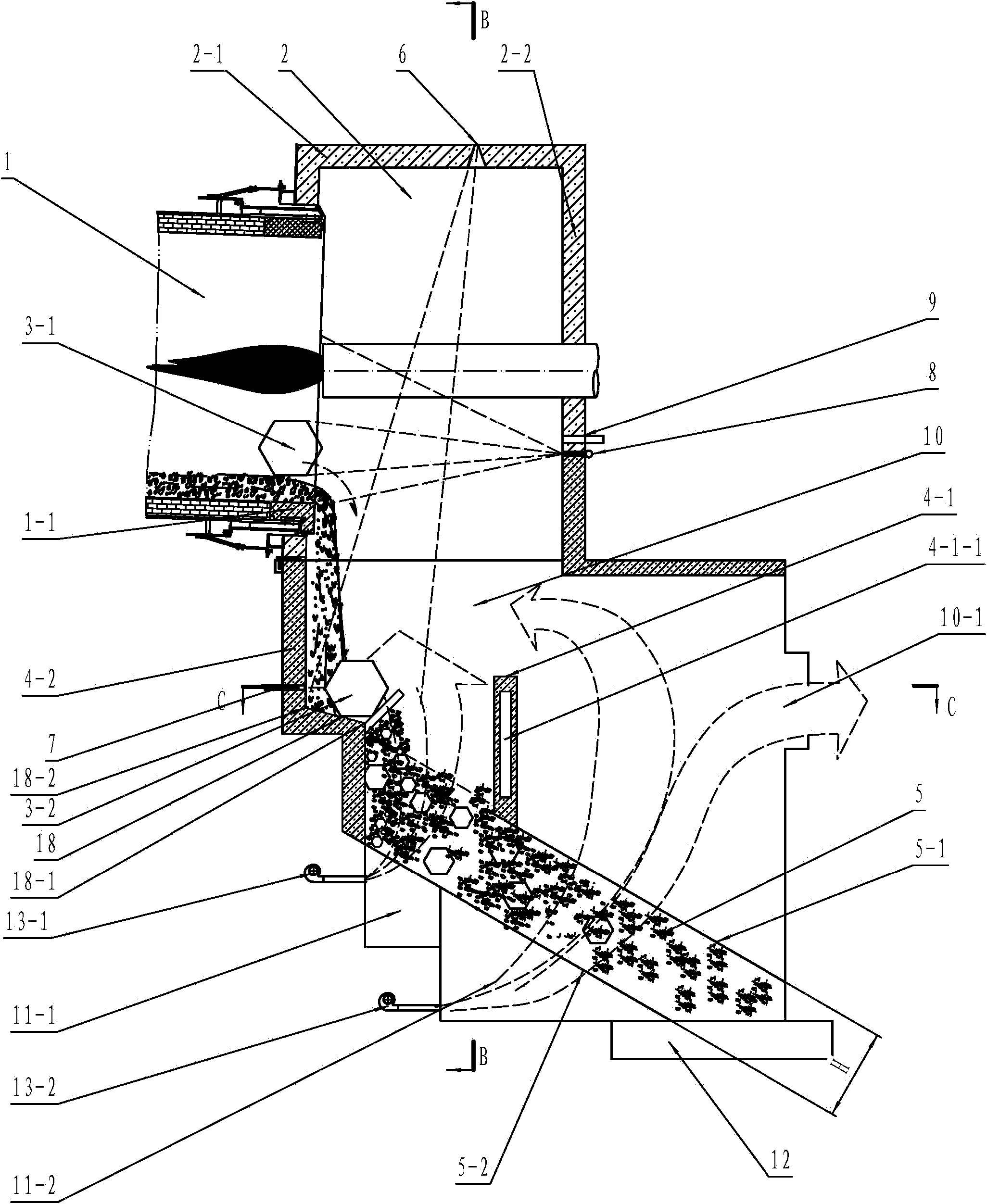
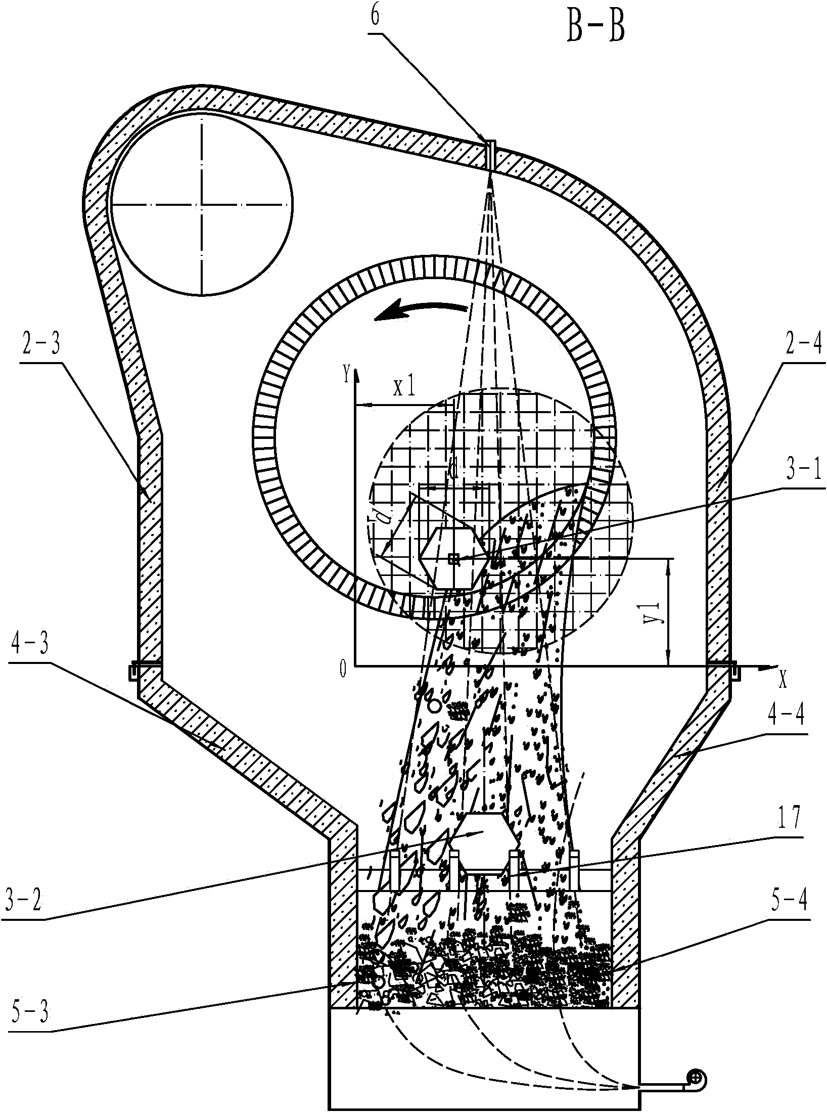
[0070] See figure 1 and figure 2 , is the front structural schematic diagram and the B-B structural schematic diagram of the belt cooler of the present invention. The material fired from the rotary kiln 1 is discharged into the chute 5 through the drainage of the drainage wall, and the material in the chute 5 slides from the inlet end of the chute to the outlet end of the chute by its own weight and is discharged through the unloader 12. When the material is falling, the cooling gas provided by the fan 13-1 and the fan 13-2 cools down the temperature of the material in the chute, so as to achieve the purpose of cooling the material. It can be seen that the entire conveyor belt cooler is a non-powered conveying system, and the conveying of materials depends entirely on the gravity of the materials. At the end, the belt cooling machine cannot handle it by itself, and it will only cause the consequence of blocking the chute, which seriously affects the production of the belt c...

Embodiment 2

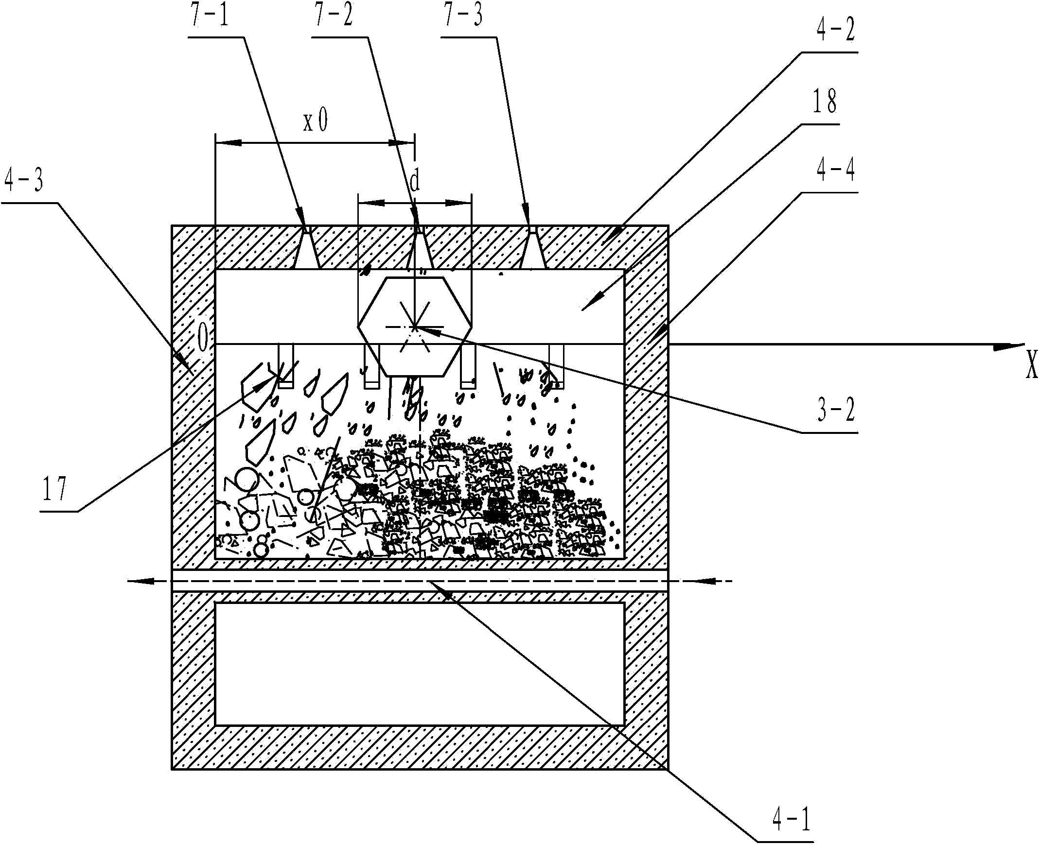
[0091] See Figure 4 and Figure 5 The difference between this embodiment and Embodiment 1 is that the filter material device in this embodiment is a grate 19, and the grate 19 is made up of a row of grate bars 19-1 arranged in the left and right direction, and one end of the grate bar 19-1 is fixed on On the front end of platform 18, the other end of grate bar 19-1 is fixed on the front drainage wall 4-1, and the distance between adjacent grate bar 19-1 is equal to size upper limit a, two grate bars at left rear two ends are respectively connected with The distance between the left drainage wall and the right drainage wall is equal to the upper limit a, so when the geometric size of the material is equal to or smaller than the upper limit a, the material can pass through the gap; when the geometric size of the material is greater than the upper limit a, that is, when the material When being a bulk material, the bulk material is grated out by the grate 19 and left on the platfo...

Embodiment 3

[0095] The difference between this embodiment and Embodiment 1 and Embodiment 2 is that the belt cooler in this embodiment is also equipped with a material level detection device and a discharge controller on the basis of Embodiment 1 and Embodiment 2, such as Figure 9 and Figure 10 As shown, the material level detection device detects the material level at the inlet end of the chute in real time, and adjusts the material level at the inlet end of the chute by controlling the unloading speed of the unloader through the unloading controller, thereby preventing the material level at the inlet end of the chute from being too high. When the position is close to or equal to the height of the platform 18, the effect of the rake-shaped heat-resistant nails or the grate (filter) will be weakened or lost, resulting in the accumulation of materials on the platform and the filter, and small pieces of material cannot fall into the At the inlet end of the chute, when the filter material ...


PUM


Abstract

The invention provides a sliding belt cooling machine which can overcome the defect that a bulk material easily blocks the sliding belt cooling machine at random in the prior art. The sliding belt cooling machine is characterized in that a rear drainage wall comprises a platform which can extend to a cavity of a drainage section, wherein the left and right ends of the platform are respectively connected with a left drainage wall and a right drainage wall; and the front end of the platform facing to the cavity of the drainage section is provided with a filtering material device used for grating a bulk material, and the sliding belt cooling machine also comprises a first bulk material processing unit used for fracturing the grated bulk material. The sliding belt cooling machine is provided with the filtering material device used for grating the bulk material and the first bulk material processing unit used for fracturing the grated bulk material, thereby eliminating the hidden danger of blockage downspouting of the bulk material, and ensuring smooth running of a material in a chute.

Description

technical field [0001] The invention relates to a material cooling device, in particular to a belt cooler used for cooling materials after firing in metallurgy, chemical industry and cement building materials industry. Background technique [0002] The cooling machine is an indispensable and important equipment in the calcining system of metallurgy, chemical industry and cement building materials. Its main function is to cool the hot material fired by the rotary kiln to the temperature allowed by the subsequent processes of transportation, storage and grinding, so as to ensure Normal continuous production; at the same time, the cooler is also a heat exchange device, which requires maximum recovery and utilization of the heat contained in the material to improve the thermal efficiency of the system. [0003] Existing coolers using chute, such as the utility model patent with the patent number ZL200920223139.7, the material slides down inside the chute by its own gravity, and ...

Claims


Application Information

Patent Timeline
Patent Type & Authority Applications(China)
IPC IPC(8): F27D15/02F27D21/00F27D21/04F27D19/00
Inventor 高玉宗
Owner 高原晨曦
Why Eureka
Try Eureka