Transfer device

A transfer device and chute technology, applied in the direction of transportation and packaging, chute, conveyor objects, etc., can solve the problems of motor burnout, affecting the stable supply of production materials, easy to block the chute, etc., to avoid blocking the chute.

Inactive Publication Date: 2011-11-23
LAIWU IRON & STEEL GRP
View PDF5 Cites 2 Cited by
  • Summary
  • Abstract
  • Description
  • Claims
  • Application Information

AI Technical Summary

Problems solved by technology

However, it is unavoidable that there are large pieces of sundries mixed in the production materials. The large sundries are easy to block the chute. Even if they flow through the chute smoothly, they are easy to scratch the belt on the belt conveyor, causing the motor to burn out, thus affecting the stability of normal production materials. supply

Method used


Image

  • Transfer device
  • Transfer device
  • Transfer device

Examples


Embodiment 1

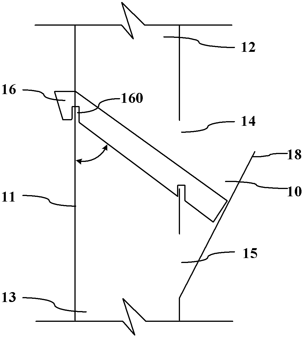
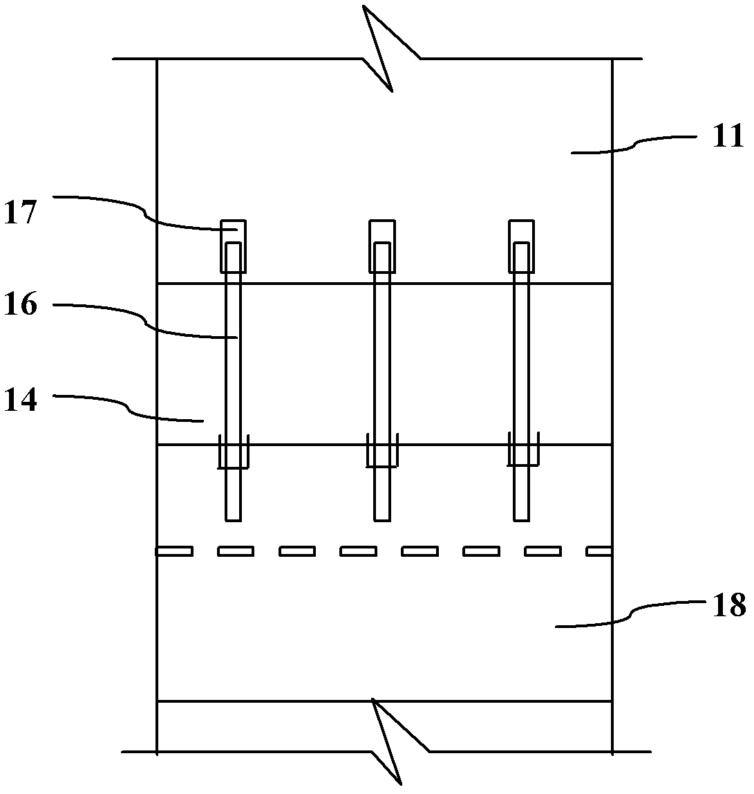
[0029] Such as figure 1 and figure 2 As shown, the embodiment of the present invention provides a kind of transfer device, comprises chute 11, material baffle plate 18 and grate plate 16, wherein, chute 11 is arranged between belt conveyor; Material baffle plate 18 is arranged on the outer wall of chute 11, and Surrounded by the outer wall of the chute 11 to form a blocking bin 10, the bottom of the chute 11 and the bottom of the blocking bin 10 are provided with a material return port 15, and the corresponding position with the opening of the blocking bin 10 is provided with a bulk outlet 14; The plate 16 is obliquely arranged inside the chute 11 , and the lower end of the grating plate 16 stretches to the material retaining plate 18 through the bulk opening 14 .

[0030] When the above-mentioned transfer device transmits the production material, the production material enters the chute 11 from the feed port 12, and when passing through the grating plate 16, part of the sol...

Embodiment 2

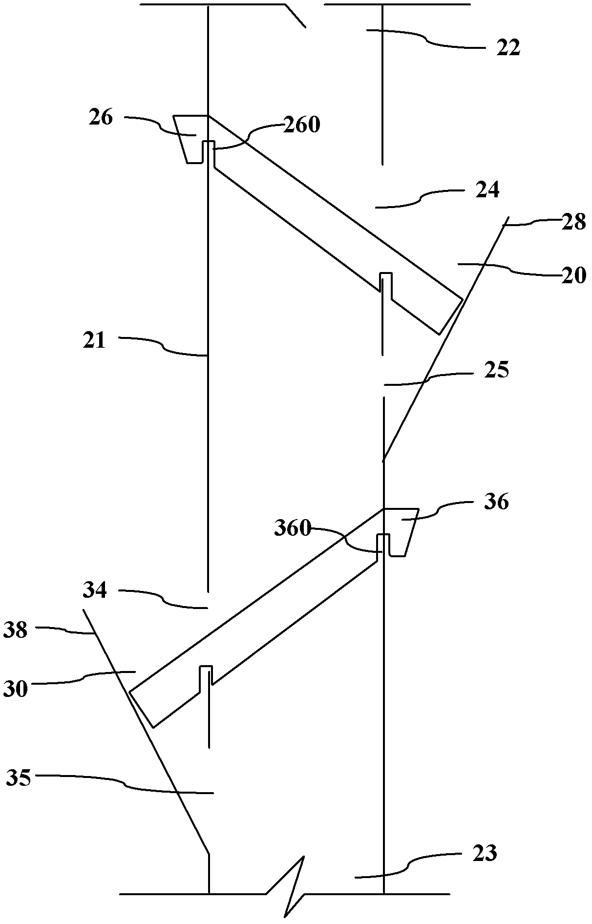
[0036] Such as image 3 As shown, the embodiment of the present invention specifically introduces the situation that two bulk outlets and a material return port are provided on the chute.

[0037] The transfer device comprises a chute 21, a first baffle plate 28, a second baffle plate 38, a first baffle plate 26 and a second baffle plate 36, wherein: the chute 21 is arranged between belt conveyors; the first material baffle plate 28 and the second baffle plate 38 are arranged on the outer wall of the chute 21 respectively, and surround the first chute 20 and the second chute 30 with the outer wall of the chute 21 respectively, the bottom of the chute 21 and the first chute 20 The corresponding position is provided with the first material return port 25, and the opening corresponding to the first blocking bin 20 is provided with the first bulk outlet 24, and the corresponding position of the chute 21 and the bottom of the second blocking bin 30 is provided with the first The s...


PUM


Abstract

The embodiment of the invention discloses a transfer device, which comprises a chute, a material baffle plate and a grating plate, wherein the material baffle plate is arranged on the outer wall of the chute, and a material blocking cabin is enclosed by the material baffle plate and the outer wall of the chute; a material return opening is formed at the corresponding position between the chute and the bottom of the material blocking cabin; a large block outlet is formed at the corresponding position of the opening of the material blocking cabin; the grating plate is obliquely arranged inside the chute; and the lower end of the grating plate passes through the large block outlet and then is extended to the material baffle plate. When the transfer device conveys production materials, the production materials is fed into the chute from a material inlet; when the production materials pass through the grating plate, solid disperse materials flow to a material outlet through the gaps of the grating plate; large impurities in the production materials cannot pass through the grating plate; the grating plate is obliquely arranged, so that the large impurities flow through the large block outlet and then flow to the material blocking cabin along the grating plate; and the large impurities in the material blocking cabin can be timely cleared. In the device, due to the arrangement of the grating plate and the large block outlet, the large impurities in the production materials can be directly led out of the chute, so that the large impurities are prevented from blocking the chute.

Description

technical field [0001] The invention relates to the field of material transfer equipment, and more specifically relates to a transfer device for removing large pieces from solid bulk materials between belt conveyor chutes in continuous production. Background technique [0002] Belt conveyor is the abbreviation of belt conveyor. The belt conveyor uses the continuous or intermittent movement of the conveyor belt to transport various items of different weights. A transfer device is usually set up between continuous production belt conveyors to facilitate the transportation of production materials. [0003] The existing transfer device is usually a chute, which is welded by ordinary steel plates. The production practice has proved that the solid bulk material in the production material can be smoothly transported to the next-level belt conveyor through the chute. However, it is unavoidable that there are large pieces of sundries mixed in the production materials. The large sun...

Claims


Application Information

Patent Timeline
IPC IPC(8): B65G47/52B65G11/02
Inventor 吕海滨刘丰生蔡祥奎
Owner LAIWU IRON & STEEL GRP
Why Eureka
Try Eureka