Method for detecting quality of conductive sliding ring

A quality inspection method and technology for conductive slip rings, which are used in the measurement of electrical variables, measuring devices, and resistance/reactance/impedance measurements, etc., can solve the problem of not being able to show the change in the contact resistance between the brush and the slideway of the conductive slip ring.

Inactive Publication Date: 2012-09-26
HARBIN INST OF TECH
View PDF5 Cites 21 Cited by
  • Summary
  • Abstract
  • Description
  • Claims
  • Application Information

AI Technical Summary

Problems solved by technology

[0003] The purpose of the present invention is to solve the problem that the current conductive slip ring detection method cannot show the total dynamic resistance of the conductive slip ring and the change of the contact resistance between the brush and the slideway, and provide a conductive slip ring quality detection method

Method used


Image

  • Method for detecting quality of conductive sliding ring
  • Method for detecting quality of conductive sliding ring
  • Method for detecting quality of conductive sliding ring

Examples


specific Embodiment approach 1

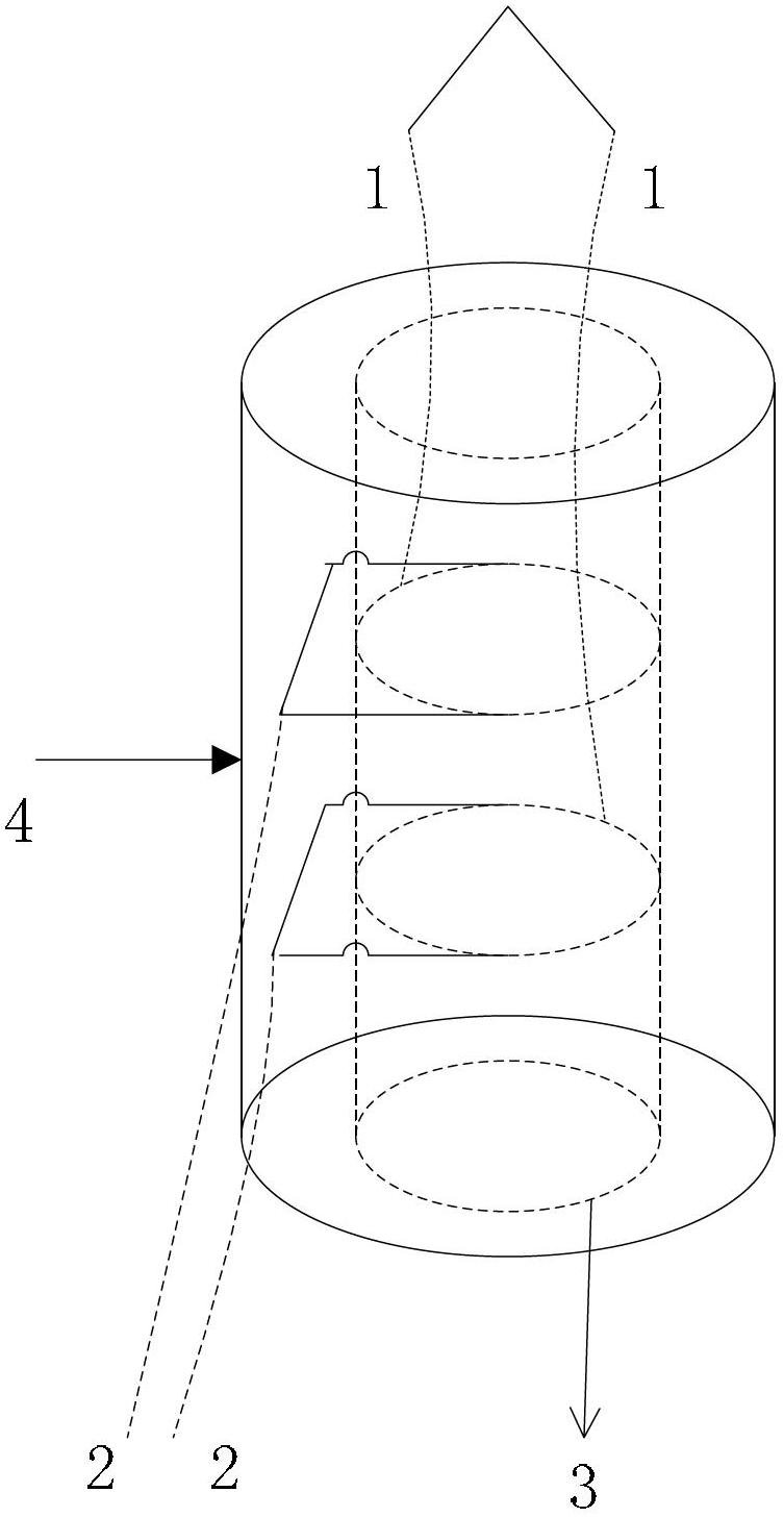
[0021] Specific implementation mode one: combine figure 1 and figure 2 Describe this embodiment mode, a kind of conductive slip ring quality detection method described in this embodiment mode, it comprises concrete steps as follows:

[0022] Place the conductive slip ring to be tested on the conductive slip ring test tool, so that the conductive slip ring runs at a constant speed of speed ω, and measure the dynamic resistance of the measured conductive slip ring as y(t) during the rotation of the conductive slip ring;

[0023] The rotation period of the above-mentioned conductive ring is T, θ 0 is the initial phase at the beginning of the test;

[0024] According to the total resistance of the conductive ring actually connected to the circuit is

[0025] R r ( t ) = R T 2 · [ - ...

specific Embodiment approach 2

[0036] Specific embodiment 2: This embodiment is a further limitation of the quality detection method of a conductive slip ring described in Embodiment 1. The total resistance R of the conductive ring actually connected to the circuit r The expression for (t) is obtained by the following method:

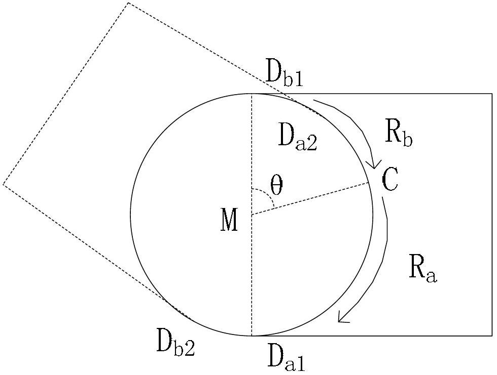
[0037] Define the contact point between the conductive ring lead wire 1 and the conductive slip ring as point C, point D a and point D b They are the two contact points between the "∏" type brush and the conductive ring, point M is the center position of the conductive ring, then point C and point D a The resistor between R a , point C and point D b The resistor between R b , R a with R b Connected in parallel, the rotation angle θ of the conductive ring corresponding to the time t is the angle formed by the line segment MC and the line segment MD, which is an acute angle;

[0038] R r (t), θ and R have the following relationship:

[0039] R ...

specific Embodiment approach 3

[0044] Specific embodiment three: This embodiment is a further limitation of the quality detection method of a conductive slip ring described in the first embodiment. According to the comparison between the ideal dynamic resistance R(t) of the conductive slip ring to be tested and the actual measured dynamic resistance y( t) and parameter R, calculate the resistance equivalent DC component R of the conductive slip ring 0 The process is:

[0045] Step 1. Obtain the ideal dynamic resistance change curve according to the ideal dynamic resistance R(t), obtain the actual dynamic resistance change curve according to the actually measured dynamic resistance y(t), discretize the two dynamic resistance change curves respectively, and the sampling interval is ΔT, Then the ideal periodic sequence R(i) is obtained after the ideal dynamic resistance change curve is discretized, i=1, 2, ... m; m is a natural number; the actual measurement sequence y(k) is obtained after the actual dynamic r...


PUM


Abstract

The invention provides a method for detecting the quality of a conductive sliding ring, relating to a method for detecting the conductive sliding ring, and solving the problem that the conventional method for detecting the conductive sliding ring cannot represent the change of the total dynamic resistance of the conductive sliding ring and the contact resistance between an electric brush and a sliding way. The method comprises the following specific steps of: placing a conductive sliding ring to be detected on a conductive sliding ring test tool to enable the conductive sliding ring to be operated at a constant rotation speed omega; and measuring a dynamic resistance y(t); according to the total resistance of the conductive ring, obtaining a total resistance R of a circle of the conductive ring to be detected, and calculating to obtain a resistance equivalent direct-current component R0 of the conductive sliding ring by comparing the ideal dynamic resistance with the actually measured dynamic resistance y(t) and the parameter R; solving to obtain a residual effective value rho of the conductive sliding ring to be detected according to the parameters R and R0, wherein the rho represents the quality of a process for manufacturing the electric brush of the conductive sliding ring and the conductive sliding ring; and calculating to obtain a mean value and a maximum fluctuation delta Rmax according to the y(t), and obtaining a fluctuation peak value Rpp according to the parameter R, wherein the material used by the conductive ring and the conductivity are reflected by the mean value, the maximum fluctuation delta Rmax and the fluctuation peak value Rpp. The method for detecting the quality of the conductive sliding ring provided by the invention is applicable to the quality detection of the conductive sliding ring.

Description

technical field [0001] The invention relates to a detection method for a conductive slip ring. Background technique [0002] Conductive slip ring is a precision power transmission device that realizes signal and current transmission between two relatively rotating components. It is widely used in various testing, automatic control, inertial navigation systems and other equipment and other occasions. The dynamic resistance of the conductive slip ring will have a serious impact on the stability and reliability of its work, and it is an important indicator reflecting the quality of the conductive slip ring product. The current conductive slip ring detection method only detects the maximum value, minimum value and variation range of its dynamic resistance, and cannot express the specific change of the total dynamic resistance of the conductive slip ring and the contact between the brush and the slideway that directly reflects the manufacturing process level of the conductive sli...

Claims


Application Information

Patent Timeline
Patent Type & Authority Applications(China)
IPC IPC(8): G01R27/02
Inventor 关宇东提纯利滕艺丹黄博闻韩媞陈家鑫周葳徐迪
Owner HARBIN INST OF TECH
Why Eureka
Try Eureka