Method and system for monitoring basic structure of wind power generation equipment

A technology for wind power generation equipment and infrastructure, which is used in the monitoring of wind turbines, wind energy generation, and the configuration of installing/supporting wind turbines. Effects of pressure on data storage and processing

Active Publication Date: 2020-03-10
GUANWEI MONITORING TECH WUXI CO LTD
View PDF4 Cites 0 Cited by
  • Summary
  • Abstract
  • Description
  • Claims
  • Application Information

AI Technical Summary

Problems solved by technology

[0005] In view of this, the embodiment of the present invention provides a monitoring method and system for the basic structure of wind power generation equipment to solve the problem that existing monitoring methods are difficult to accurately reflect tower instability factors caused by factors such as extrusion and wear in the basic structure , and the problem of a large amount of monitoring data

Method used


Image

  • Method and system for monitoring basic structure of wind power generation equipment
  • Method and system for monitoring basic structure of wind power generation equipment
  • Method and system for monitoring basic structure of wind power generation equipment

Examples


Embodiment 1

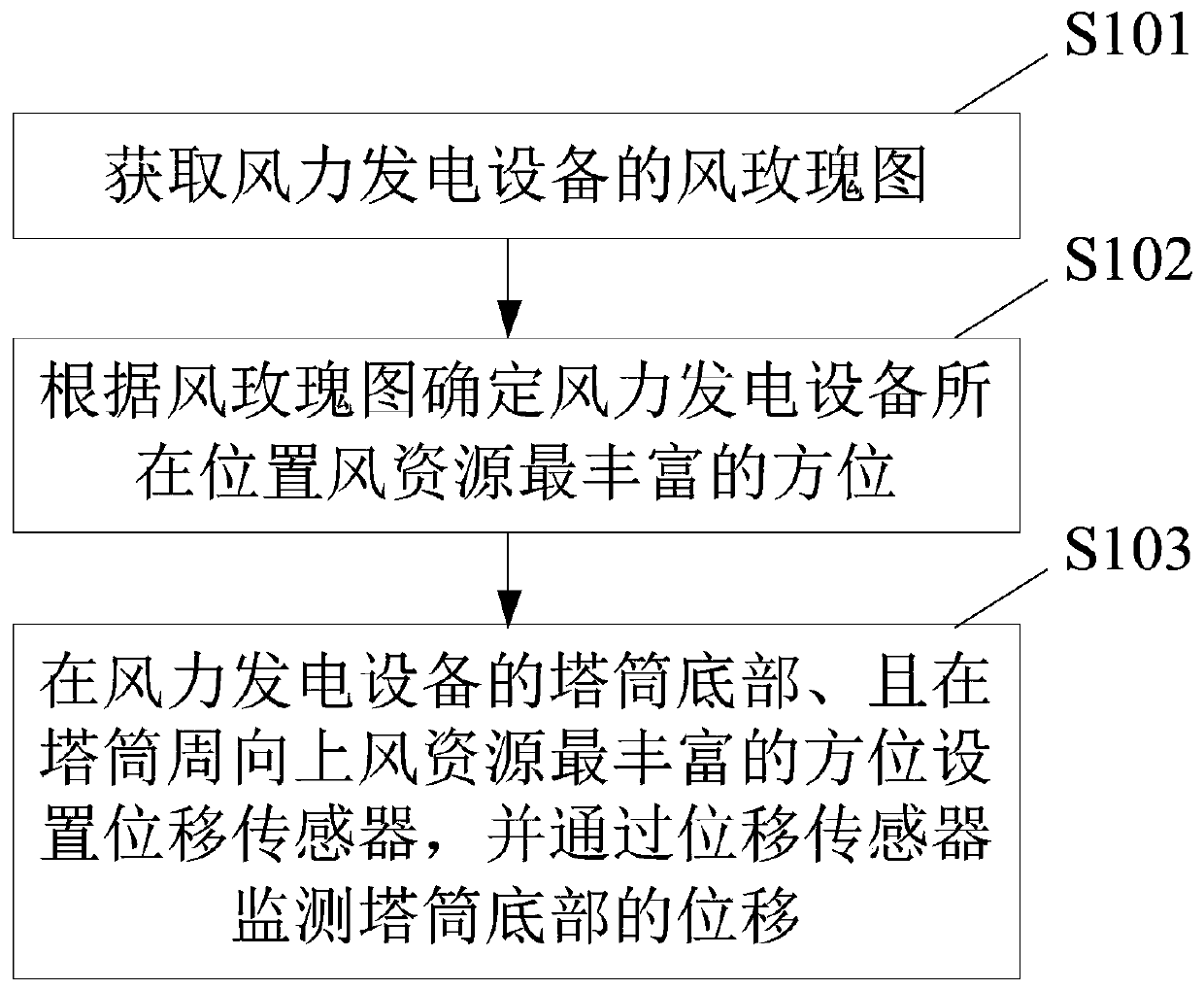
[0030] Figure 3A A flow chart of a method for monitoring the infrastructure of wind power generation equipment according to an embodiment of the present invention is shown. Such as Figure 3A As shown, the method includes the following steps:

[0031] S101: Obtain a wind rose diagram of the wind power generation equipment.

[0032] S102: Determine the location where the wind power generation equipment is located with the most abundant wind resources according to the wind rose diagram.

[0033] The wind rose diagram in the present application can be the commonly understood "wind direction frequency rose diagram" (also referred to as "wind direction rose diagram", "wind direction diagram"), or it can be a wind speed rose diagram, or a wind energy rose diagram.

[0034] The wind direction frequency rose diagram can reflect the percentage of the number of occurrences of various wind directions in all observations within a certain period of time; for example Figure 3B The great...

Embodiment 2

[0042] Figure 4A A flow chart of another method for monitoring the infrastructure of wind power generation equipment according to an embodiment of the present invention is shown. Such as Figure 4A As shown, the method includes the following steps:

[0043] S201: Obtain a wind rose diagram of the wind power generation equipment.

[0044] S202: Determine the location where the wind power generation equipment is located with the most abundant wind resources according to the wind rose diagram.

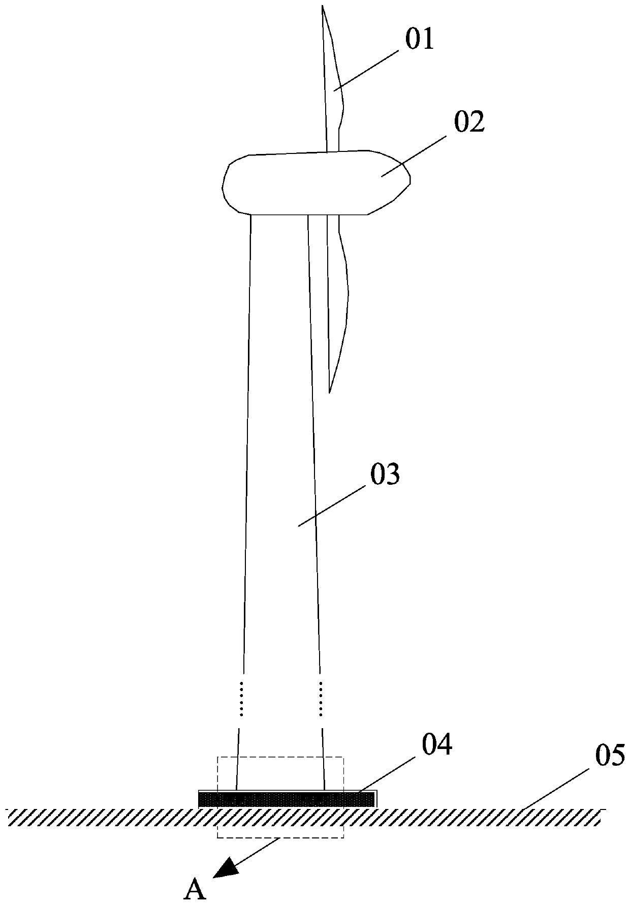
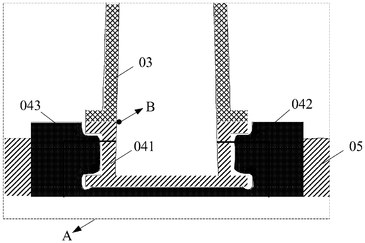
[0045] S203: At the bottom of the tower of the wind power generation equipment, and on the circumference of the tower, the direction with the most abundant wind resources.

[0046] For the above steps S201, S202 and S203, please refer to steps S101, S102 and S103 for details.

[0047] S204: Determine whether the displacement of the tower bottom is greater than a first preset threshold. When the displacement of the bottom of the tower is greater than the first preset threshold, perfo...

Embodiment 3

[0058] Figure 5 A schematic structural diagram of a monitoring system for a wind power generation equipment infrastructure according to an embodiment of the present invention is shown. The monitoring system can be used to implement the monitoring method described in the first or second embodiment. Such as Figure 5 As shown, the monitoring system includes a first server 10 , a displacement sensor 20 , a data collector 30 and a second server 40 .

[0059] The first server 10 is configured to acquire a wind rose diagram of the wind power generation equipment, and the wind rose diagram includes at least one of a wind direction frequency rose diagram, a wind speed rose diagram, or a wind energy rose diagram. According to the wind rose diagram, the azimuth with the most abundant wind resource is determined where the wind power generation equipment is located, and the azimuth where the displacement sensor is set is determined to be the azimuth with the most abundant wind resource...


PUM


Abstract

The invention discloses a method and system for monitoring the foundation structure of a wind power generation device, wherein the method comprises the following steps of: acquiring a wind rose diagram of the wind power generation device, wherein the wind rose diagram comprises at least one of a wind direction frequency rose diagram, wind speed rose diagram or wind energy rose diagram; determininga direction with a most abundant wind resource of the position where the wind power generation device is located according to the wind rose diagram; arranging a displacement sensor at the bottom of atower barrel of the wind power generation device and in the direction with the most abundant wind resource in the circumferential direction of the tower barrel, wherein the displacement of the bottomof the tower barrel is monitored by the displacement sensor. According to the invention, the displacement sensor monitors the displacement of the bottom of the tower barrel, and the displacement sensor is arranged at the bottom of the tower barrel of the wind power generation device and can accurately reflect unstable conditions of the tower barrel caused by factors such as extrusion, abrasion and the like in the foundation structure; the displacement sensor is arranged in the direction with the most abundant wind resource in the circumferential direction of the tower barrel, the utilizationrate of the displacement sensor is higher, and less monitoring results can be generated.

Description

technical field [0001] The invention relates to the technical field of wind power generation equipment, in particular to a monitoring method and system for the basic structure of wind power generation equipment. Background technique [0002] With the continuous development of wind power generation technology, the application scale of wind power generation equipment is increasing day by day. Wind power generation equipment includes wind turbines and fixed equipment. figure 1 A schematic structural diagram of a wind power generation device is shown. Such as figure 1 As shown, the wind power generation equipment mainly includes a blade 01, a hub 02, a generator, a tower 03, a basic structure 04, and the like. Wherein the blade 01 and the hub 02 form a wind wheel, and the wind wheel is rotated by wind force, driving the head of the generator to rotate to generate electric energy. The tower 03 is used to erect the wind rotor and the generator in an open area with abundant win...

Claims


Application Information

Patent Timeline
Patent Type & Authority Patents(China)
IPC IPC(8): F03D13/20F03D17/00
CPCF03D13/20F03D17/00Y02E10/72Y02E10/728
Inventor 杨浚嘉李林
Owner GUANWEI MONITORING TECH WUXI CO LTD
Why Eureka
Try Eureka