Charging socket and switch assembly

A switch combination, charging socket technology, applied in electrical components, circuits, contact parts, etc., can solve the problems of inconvenience and inability to control the positive pole of the product that needs to be charged, easy to damage, etc.

Inactive Publication Date: 2012-09-26
中山市创建电子元件有限公司
View PDF4 Cites 2 Cited by
  • Summary
  • Abstract
  • Description
  • Claims
  • Application Information

AI Technical Summary

Problems solved by technology

In the existing charging socket, the control terminal can only control the on or off of the negative power supply of the product to be charged, but cannot control the on or off of the positive power supply of the product to be charged, otherwise, an instantaneous short circuit will occur when the plug is inserted. It may damage the product; even if the control terminal controls the on or off of the negative pole of the power supply of the product, because there will be an instant bipolar interconnection between the external charging power supply and the product to be charged, when the plug is inserted, it will be short-circuited for a moment and easily damaged. For charging products, the existing charging socket is purely a short-circuit charging socket and only a single charging socket. If the product needs to have a switch function, it must be connected to the switch again, which is really inconvenient

Method used


Image

  • Charging socket and switch assembly
  • Charging socket and switch assembly
  • Charging socket and switch assembly

Examples


Embodiment Construction

[0045] The present invention will be further described below in conjunction with accompanying drawing.

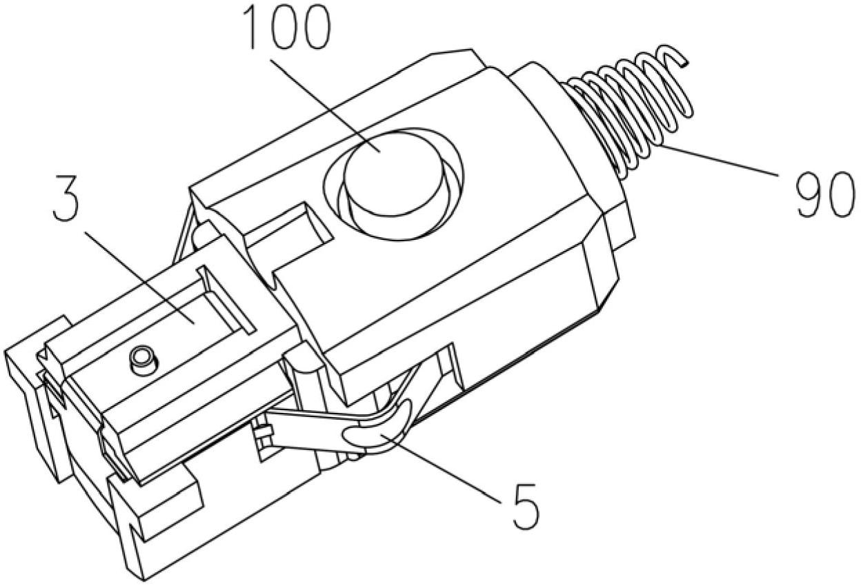
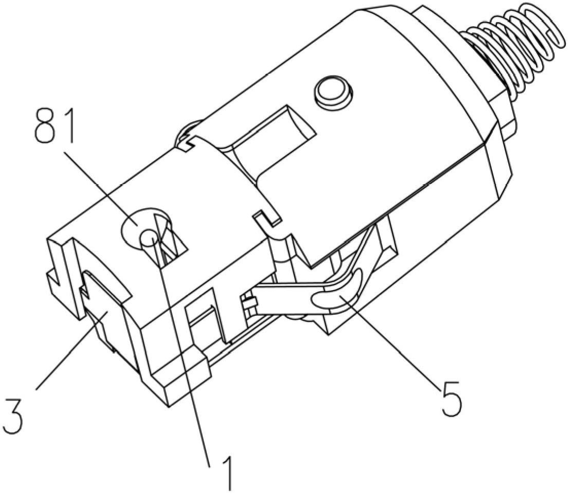
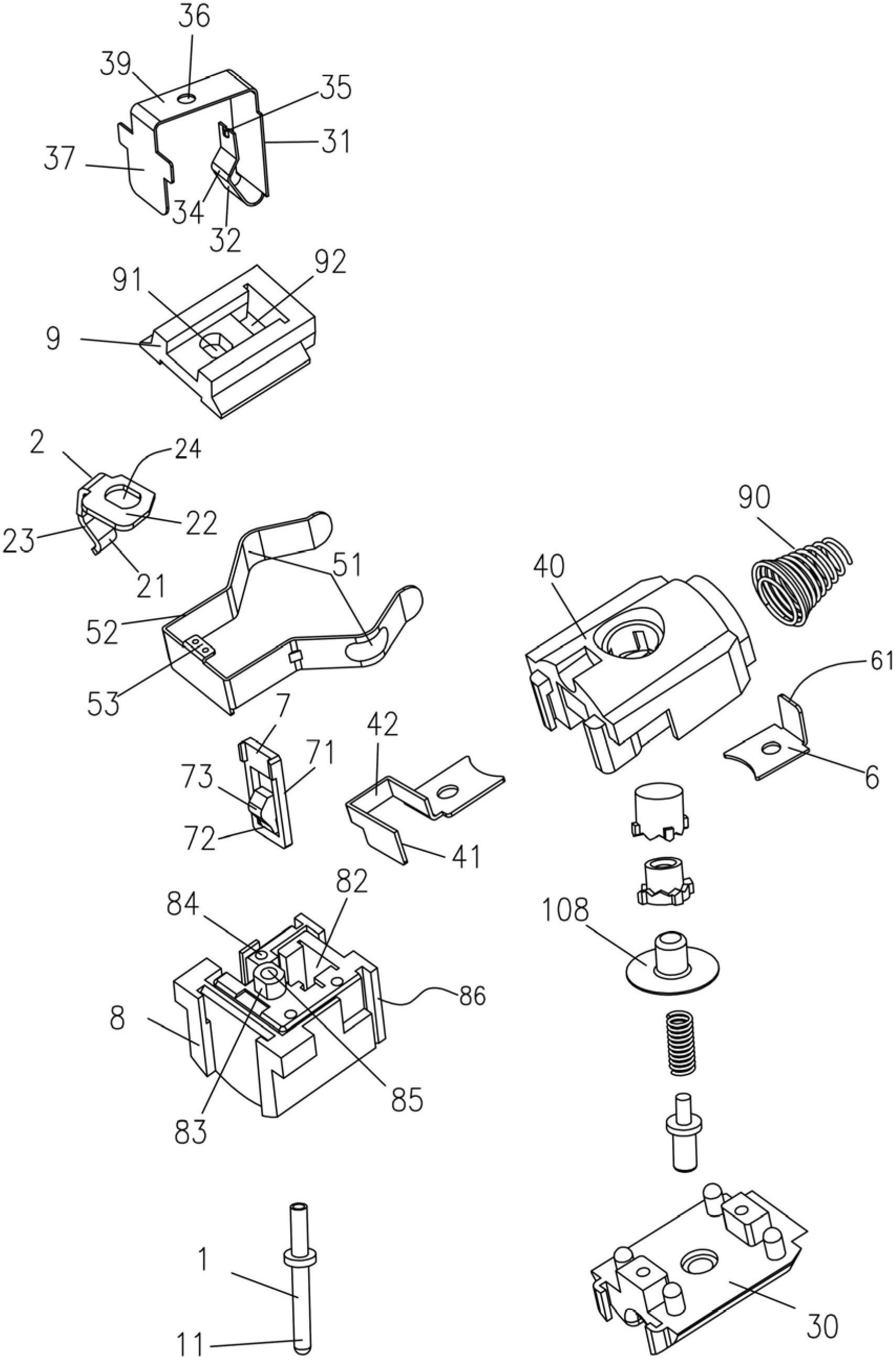
[0046] Such as Figure 1 to Figure 26 As shown, a charging socket and switch assembly includes an insulating housing, a first terminal 1, a second terminal 2, a third terminal 3, a fourth terminal 4 and a top opening 7, and the insulating housing has a charging plug 200 inserted into the socket 81, the socket 81 has an open end 811 and a closed end 812 opposite to the open end, the first terminal 1 is provided with a first contact portion located in the socket 81 and in contact with the inner wall 201 of the charging plug 11. The second terminal 2 is provided with a second contact portion 21 located in the jack 81 and in contact with the outer wall 202 of the charging plug. A control chamber 82 is provided on the insulating housing, and the third terminal 3 is provided with a control chamber 82 located in the control chamber 82. The control part 34 and the third contact pa...


PUM


Abstract

The invention relates to a charging socket and switch assembly. The charging socket and switch assembly comprises an insulating casing, a first terminal, a second terminal, a third terminal, a fourth terminal and a top-open piece, wherein the insulating casing is provided with a jack allowing a charging plug to be plugged therein; the first terminal is provided with a first contact part positioned in the jack; the second terminal is provided with a second contact part positioned in the jack; a control room is arranged on the insulating casing; the third terminal is provided with a control part and a third contact part which are positioned in the control room; the fourth terminal is provided with a fourth contact part positioned in the control room; an insulating elastic arm is arranged on the top-open piece; the third terminal is conducted with the first terminal; the third terminal is provided with a connecting piece connected with the positive pole of a battery; a fifth terminal is fixed on the insulating casing and provided with a spring plate connected with the negative pole of the battery; and the shortest distance between the second contact part and an open end is larger than that between an elastic contact part and the open end. The charging socket and switch assembly can prevent a product requiring to be charged from being damaged by sudden short circuit at the instant of initial charging of a device.

Description

technical field [0001] The invention relates to a charging socket and a switch assembly, in particular to a non-short-circuit charging socket and a switch assembly. Background technique [0002] The non-short-circuit charging socket and switch combination is installed on the household electrical appliances and other electronic products and some control circuits that need to be charged, so as to be suitable for plugging in a certain power supply equipment, so as to use flashlights, safety lights, etc. , anti-theft equipment and household appliances, electronic products, some control circuits, toys and other products for charging. In the existing charging socket, the control terminal can only control the on or off of the negative power supply of the product to be charged, but cannot control the on or off of the positive power supply of the product to be charged, otherwise, an instantaneous short circuit will occur when the plug is inserted. It may damage the product; even if ...

Claims


Application Information

Patent Timeline
Patent Type & Authority Applications(China)
IPC IPC(8): H01R13/02H01R13/70H01R13/703H01R13/502
Inventor 朱成辉
Owner 中山市创建电子元件有限公司
Why Eureka
Try Eureka