Supercharge Your Innovation With Domain-Expert AI Agents!

Hydrodynamic bearing device

A technology of fluid dynamic pressure bearings and bearing devices, which is applied in the direction of sliding contact bearings, bearings, and rotating bearings. It can solve the problems of time-consuming and labor-intensive processing of gate marks, and reduce processing costs. damage effect

Active Publication Date: 2015-09-30
NTN CORP
View PDF8 Cites 0 Cited by
  • Summary
  • Abstract
  • Description
  • Claims
  • Application Information

AI Technical Summary

Problems solved by technology

However, in this case, if Figure 11 As shown, it is necessary to remove the central part 120 of the bottom 111 of the bottomed cylindrical formed part 110, and the processing is time-consuming and laborious.
[0015] In addition, when the mold for forming the sealing member is provided with a ring-shaped film gate (not shown), the welding line is not formed, but in this case, a ring-shaped gate trace is formed on the molding, so the gate Removal of mouth marks is time-consuming and labor-intensive

Method used


Image

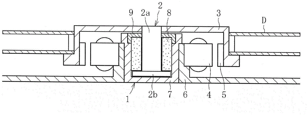
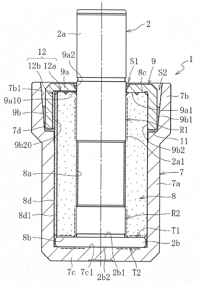
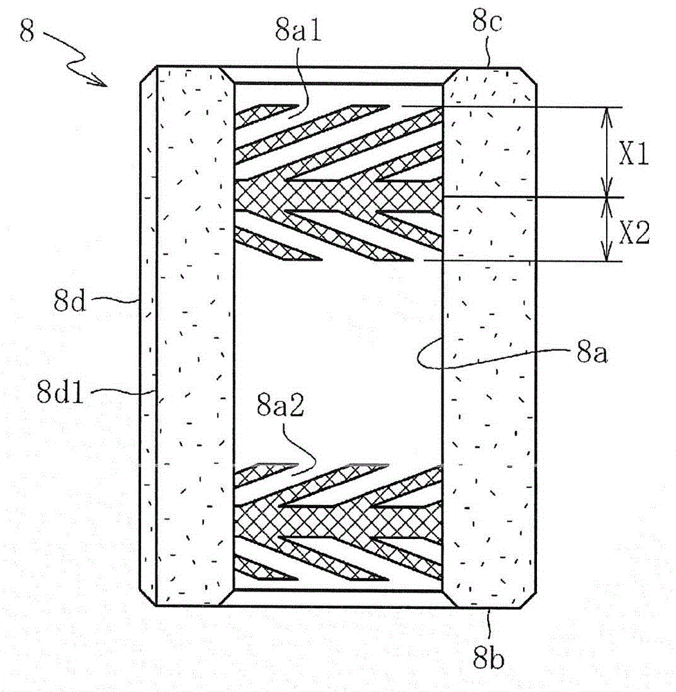
  • Hydrodynamic bearing device
  • Hydrodynamic bearing device
  • Hydrodynamic bearing device

Examples


Embodiment 1

[0103] In order to confirm the effect of the present invention, as Figure 9 As shown, a sleeve test piece 130 having the same structure as the bearing sleeve 8 of the above-mentioned embodiment was press-fitted into the inner periphery of a seal test piece 140 having the same structure as the above-mentioned seal member 9, and it was checked whether the seal test piece 140 was damaged. test. For the sealing test piece 140, an embodiment in which a welding line is formed in the middle of the axial groove in the circumferential direction (refer to Figure 5 ) and a comparative example (not shown) in which the welding wire is formed at the position in the circumferential direction of the deepest part of the axial groove. Furthermore, as the sealing test piece 140 of the example and the comparative example, various kinds of test pieces having different inner diameter dimensions of the cylindrical portion 141 , that is, various kinds of test pieces having different pressing margi...


PUM

PropertyMeasurementUnit
diameteraaaaaaaaaa

Abstract

A weld line formed by injection molding of a sealing member is formed at a circumferential position out of deepest portions of axial grooves, which form thinned portions of the sealing member (optimally, in a region of a cylindrical surface between the axial grooves in a circumferential direction). Thus, the sealing member is prevented from being provided with parts having locally markedly low strength, and hence damage to be caused by press-fitting is prevented.

Description

technical field [0001] The present invention relates to a fluid dynamic pressure bearing device in which a shaft member is relatively rotatably supported by the dynamic pressure action of lubricating oil generated in a bearing gap. Background technique [0002] For example, in the fluid dynamic pressure bearing device disclosed in Patent Document 1, a bearing sleeve made of sintered metal is fixed to the inner circumference of a bottomed cylindrical housing, and a shaft member is inserted into the inner circumference of the bearing sleeve. The shaft member is supported by the dynamic pressure of lubricating oil generated in the radial bearing gap between the shaft and the inner peripheral surface of the bearing sleeve. A seal member is fixed to an end portion of the bearing sleeve, and the lubricating oil filled inside the housing is sealed by the seal member. Specifically, the seal member integrally has a disc-shaped first seal portion abutting on the end surface of the be...

Claims


Application Information

Patent Timeline
Patent Type & Authority Patents(China)
IPC IPC(8): F16C33/74F16C17/10
CPCF16C32/0629F16C33/74F16C17/107F16C33/1085F16C33/743F16C33/745F16C2220/04
Inventor 铃木航洋丹羽洋里路文规尾藤仁彦稻塚贵开
Owner NTN CORP
Features
  • R&D
  • Intellectual Property
  • Life Sciences
  • Materials
  • Tech Scout
  • Unparalleled Data Quality
  • Higher Quality Content
  • 60% Fewer Hallucinations
Learn More