
Work-piece cutting and cooling system

A cooling system and workpiece technology, which is applied in the direction of manufacturing tools, metal sawing equipment, metal processing equipment, etc., can solve the problems of reducing the working efficiency of the aluminum strip production system, increasing the manufacturing cost of aluminum strips, and affecting continuity, etc.

Inactive Publication Date: 2012-10-03
东莞市润华铝业有限公司
View PDF5 Cites 2 Cited by
  • Summary
  • Abstract
  • Description
  • Claims
  • Application Information

AI Technical Summary

Problems solved by technology

In order to make the actions between the various processes coordinated and continuous, so as to improve the manufacturing efficiency of the entire aluminum bar production system, correspondingly, the equipment used in each process is required to be able to perform on-line processing actions on the aluminum bars in the production line. , as far as possible to avoid the production line being in a suspended state due to the standstill of the aluminum strips, however, the cutting and cooling device for cutting and cooling the aluminum strips delivered by the existing production line needs to keep the production line in a suspended state during cutting and cooling, and the suspension The production line will affect the continuity of the entire aluminum bar production system, thereby reducing the work efficiency of the entire aluminum bar production system and increasing the manufacturing cost of aluminum bars
[0004] Equally, when above-mentioned cutting cooling device cuts and cools other metal workpieces except aluminum bar, also there is above-mentioned same problem

Method used


Image

  • Work-piece cutting and cooling system
  • Work-piece cutting and cooling system
  • Work-piece cutting and cooling system

Examples


Embodiment Construction

[0026] In order to describe the technical content and structural features of the present invention in detail, further description will be given below in conjunction with the implementation and accompanying drawings.

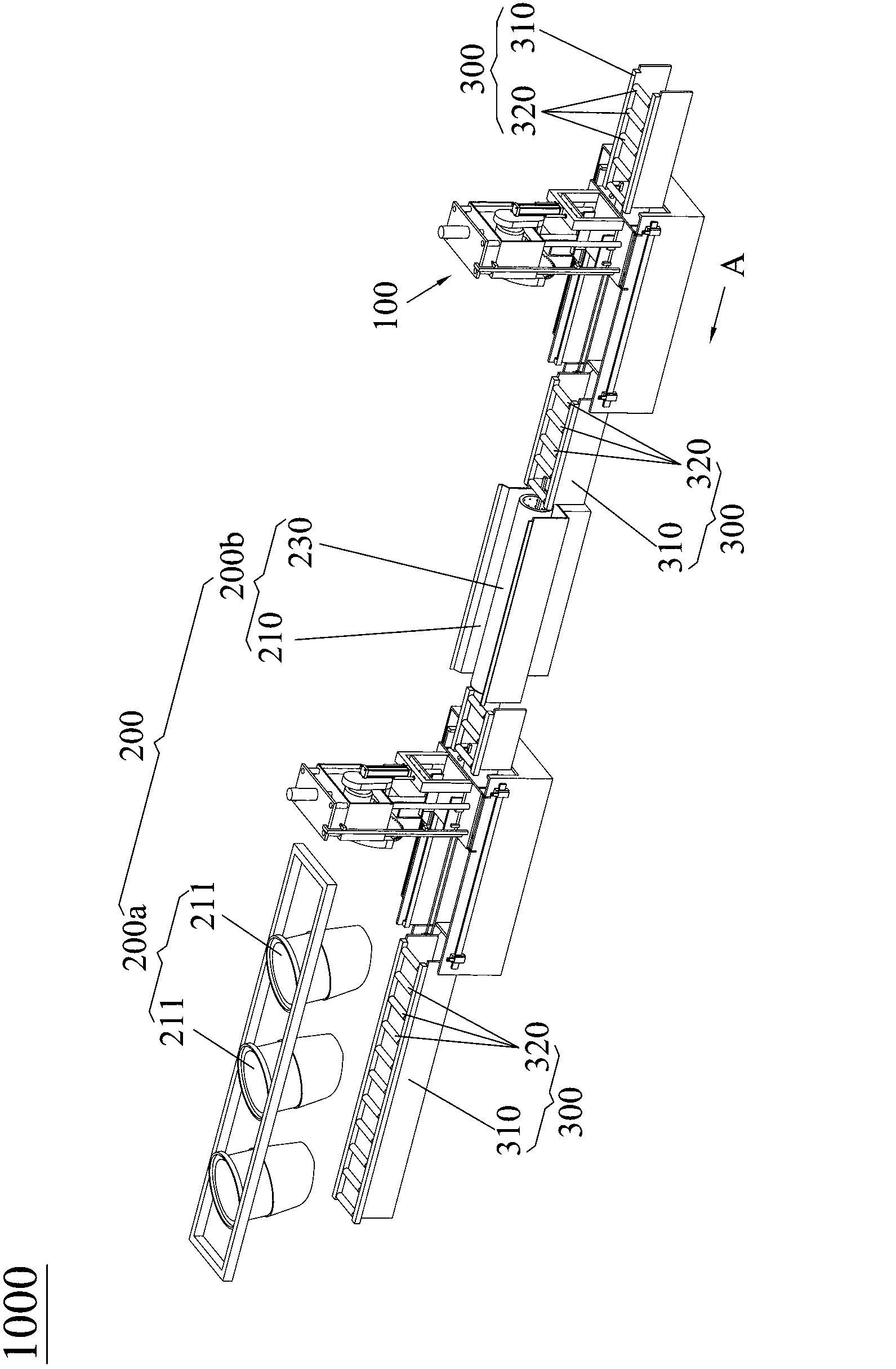
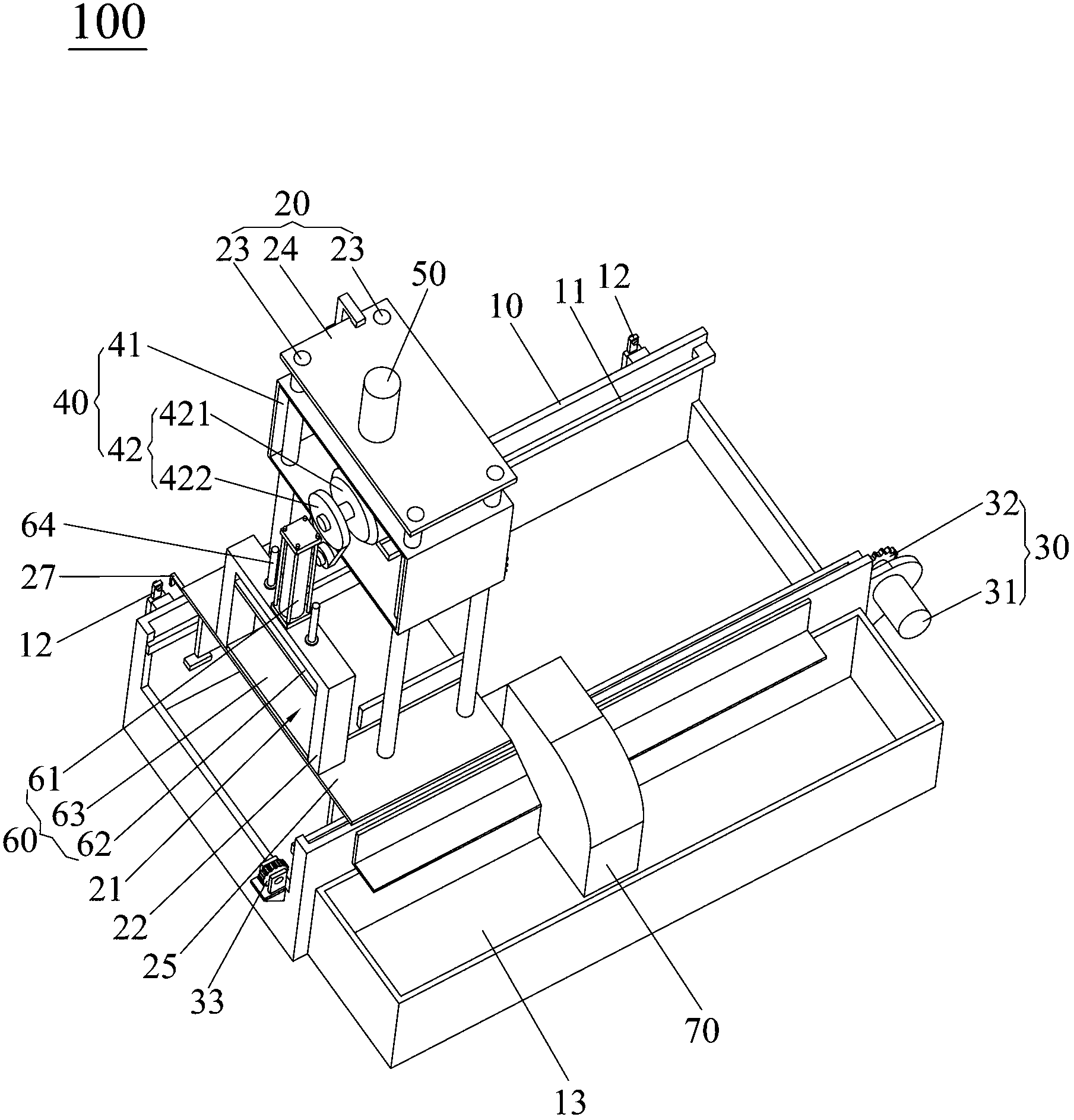
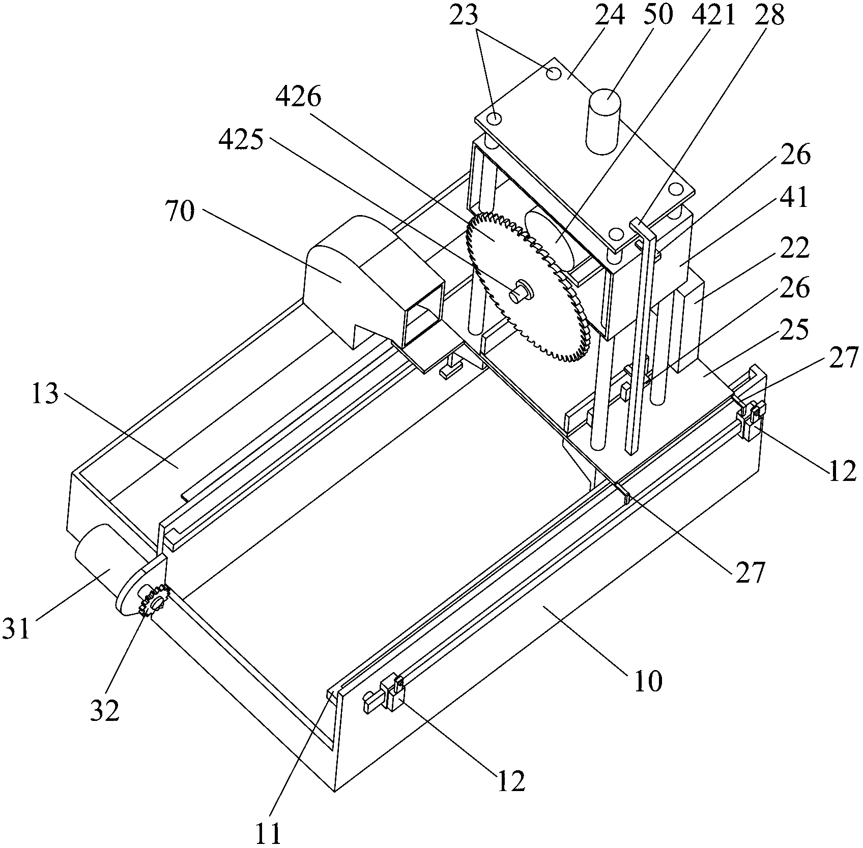
[0027] see Figure 1 to Figure 4 , the workpiece cutting cooling system 1000 of the present invention is electrically connected with the controller, the workpiece cutting cooling system 1000 is arranged on the production line 300 and cuts and cools the workpieces conveyed by the production line 300, and the production line 300 has a track 310 pivotally connected to the track The rolling element 320 on the track 310 and drives the workpiece to be transported, and the driving assembly (not shown in the figure) arranged on the track 310 and driving the rolling element 320 to rotate.

[0028]The workpiece cutting cooling system 1000 of the present invention includes a workpiece cutting device 100 for cutting workpieces conveyed by the production line 300 into workpie...


PUM


Abstract

The invention discloses a work-piece cutting and cooling system electrically connected with a controller. The work-piece cutting and cooling system comprises a work-piece cutting device and a cooling device, wherein the work-piece cutting device comprises a bed body which is mounted on a production line, a sliding frame body which is arranged on the bed body in a sliding manner and provided with a conveying channel, a driving mechanism which is arranged on the bed body and drives the sliding frame body to slide on the bed body, a cutting mechanism which is arranged on the sliding frame body and cuts a work-piece entering into the conveying channel into work-piece sections and a cutting driver which is arranged on the sliding frame body and drives the cutting mechanism to move towards the place where the work-piece inside the conveying channel exists; the cutting driver, the driving mechanism and the cutting mechanism are electrically connected with the controller; and the cooling device is located behind the work-piece cutting device along the direction in which the production line conveys the work-piece. The work-piece cutting and cooling system, disclosed by the invention, can perform cutting process and cooling on the conveying work-piece without stopping the production line. Therefore, the work-piece cutting and cooling system, disclosed by the invention, has the advantages of improving work efficiency and changing cutting length of the work-piece to satisfy with different requirements according to the need.

Description

technical field [0001] The invention relates to a workpiece cutting cooling system, in particular to a workpiece cutting cooling system capable of cutting and cooling workpieces conveyed by a production line. Background technique [0002] With the continuous development of the economy and the continuous improvement of science and technology, good conditions have been created for the vigorous development of the automation industry, thus accelerating the pace of development of the automation industry to meet the needs of future development. [0003] Among them, in the automatic manufacturing process of aluminum bars, many manufacturing processes are involved, such as the casting process of aluminum bars, the cutting process of cutting the cast aluminum bars into aluminum bar segments, and the cooling of aluminum bar segments. In order to make the actions between the various processes coordinated and continuous, so as to improve the manufacturing efficiency of the entire alumin...

Claims


Application Information

Patent Timeline
Patent Type & Authority Applications(China)
IPC IPC(8): B23D59/00B23D45/02B23D47/00
Inventor 袁淦明余巨攀叶志强余任锋
Owner 东莞市润华铝业有限公司
Learn More