
Sub handlebar of bicycle

A bicycle and auxiliary handle technology, applied in bicycle accessories, steering mechanism, transportation and packaging, etc., can solve the problems of soreness, numbness, pain, muscle strain, etc., and achieve the effect of increasing riding comfort and increasing riding efficiency.

Inactive Publication Date: 2012-10-03
杨博钦 +1
View PDF5 Cites 3 Cited by
  • Summary
  • Abstract
  • Description
  • Claims
  • Application Information

AI Technical Summary

Problems solved by technology

[0004] However, when riding for a long time, the palms, wrist joints, waist, and buttocks remain in a riding position for a long time without relaxation, which may cause soreness, numbness, pain, and muscle strain.

Method used


Image

  • Sub handlebar of bicycle
  • Sub handlebar of bicycle
  • Sub handlebar of bicycle

Examples


specific Embodiment 1

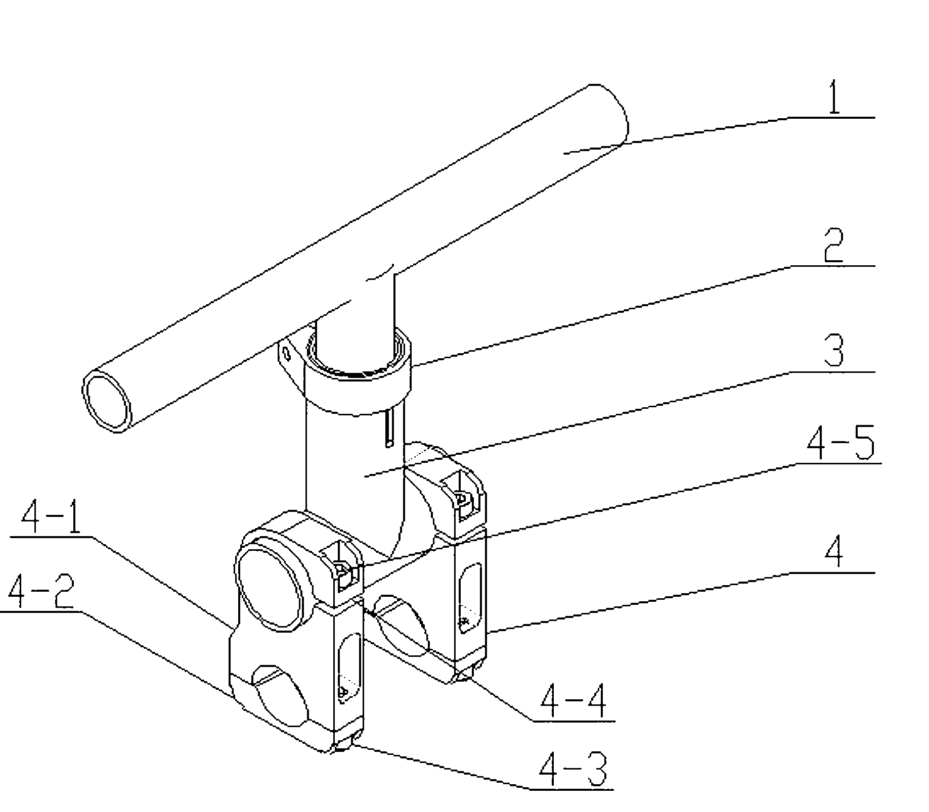
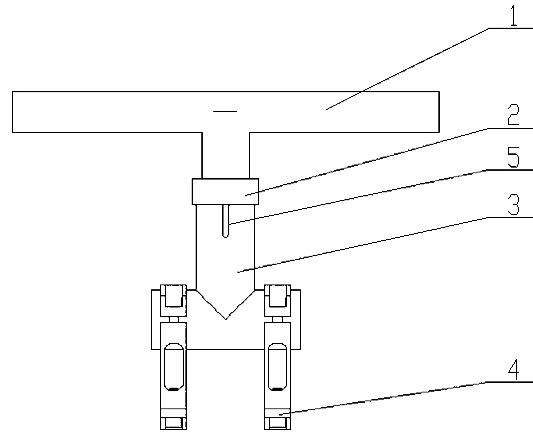
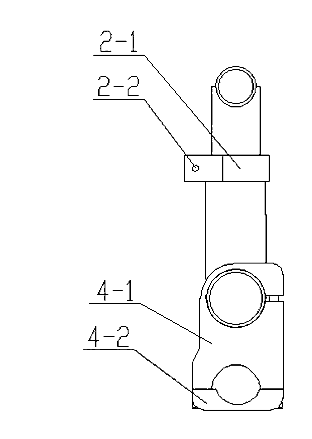
[0018] like figure 1 , figure 2 and image 3 A specific embodiment shown includes an upper T-shaped tube 1 , a tube clamp 2 , a lower T-shaped tube 3 and two tube clamps 4 .

[0019] The upper T-shaped tube 1 and the lower T-shaped tube 3 are plugged into an I-shaped main body, and the plug-in end of the lower T-shaped tube 3 is provided with a groove 5 in the axial direction of the plug-in end, and one end of the groove 5 extends to the socket. The upper T-shaped tube 1 is plugged into the lower T-shaped tube 3, and the joint between the upper T-shaped tube 1 and the lower T-shaped tube 3 is fastened by the tube clamp 2, which includes a fastening package wrapped outside the tube body. Band 2-1 and the screws 2-2 connecting the two ends of the fastening band 2-1. Tube card 2 is a common tube card.

[0020] Two ends of the beam of the lower T-shaped pipe 3 are respectively provided with a pipe clamp 4, and each pipe clamp 4 is respectively provided with two clamping openi...

specific Embodiment 2

[0022] like Figure 4 , Figure 5 and Figure 6 A kind of specific embodiment shown, the difference between this specific embodiment and specific embodiment one is that the structure of pipe clamp 4 is different, and the pipe clamp 4 that this specific embodiment adopts comprises half-pipe clamp 4-6 and half-pipe clamp 4-7 , the half-pipe clamp 4-6 and the half-pipe clamp 4-7 are respectively provided with two half-pipe openings, the two half-pipe openings of the half-pipe clamp 4-6 and the half-pipe clamp 4-7 correspond one by one, and the half-pipe clamp The two ends of 4-6 and half pipe clamp 4-7 are connected by screw 4-8.

[0023] How to use: This pair of handlebars is used to install on the main handlebar of the bicycle. Loosen the two screws 4-8, remove the lower half-pipe clamp 4-7, and buckle the half-pipe clamp 4-6 and half-pipe clamp 4-7 respectively. On the crossbeam of T-shaped pipe 3 and the main handle, screws 4-8 are screwed on to realize that the auxiliary ...


PUM


Abstract

The invention discloses a sub handlebar of a bicycle. According to the invention, the sub handlebar of the bicycle comprises an I-shaped main body, wherein pipe clips are arranged at two ends of a cross beam of the I-shaped main body; two clamping openings are formed in each pipe clip; and one clamping opening of each pipe clip is clamped on the cross beam of the I-shaped main body. The sub handlebar of the bicycle is mounted on a main handlebar; after the sub handlebar is mounted, a rider can hold the sub handlebar on straight road sections or downslope road sections and support the body through legs, feet and the upper part of the hip, so that palms, wrist joints, the waist part, shoulder parts and the lower side of the hip are relaxed. Through alternatively using the sub handlebar and the main handlebar, the riding posture can be changed, so that the muscle stressed state of each part of the body can be reasonably distributed to improve the comfort in riding and increase the riding efficiency.

Description

technical field [0001] The invention relates to a bicycle handlebar. Background technique [0002] When riding a bicycle, especially a mountain bike, the riding posture basically uses the handles, pedals, and saddle as the support points. When sitting, the weight should not be concentrated on the saddle, but should be distributed on the wrists and feet . [0003] The main handle of the existing bicycle is arranged on the standpipe above the front wheel of the bicycle. The height of the standpipe can be adjusted to adjust the height of the main handle. The adjustment of the height of the faucet is mainly to adjust the counterweight when the weight is pressed on the bicycle. , but also affect the flexibility of manipulation. When riding normally, the weight of the body should be evenly distributed on the "golden triangle" of cycling: the "handlebar", "seat cushion" and "pedal". People who don't ride bikes often or don't have the habit of cycling, because they are not ...

Claims


Application Information

Patent Timeline
Patent Type & Authority Applications(China)
IPC IPC(8): B62K21/16
CPCB62K21/125
Inventor 杨博钦陈宇
Owner 杨博钦
Learn More